
Page 154 - Power Electronic Control in Electrical Systems
P. 154
//SYS21/F:/PEC/REVISES_10-11-01/075065126-CH004.3D ± 142 ± [106±152/47] 17.11.2001 9:54AM
142 Power flows in compensation and control studies
It should be pointed out that the SPS in Figure 4.3(b) has the phase angle tapping
in the primary winding and that its effect may be incorporated in the phase angle y m .
Hence, the Jacobian terms corresponding to P l , Q l , P m and Q m are derived with
respect to y m , as opposed to f, using equations (4.81)±(4.82). For cases when the
phase shifter angle is in the secondary winding the corresponding Jacobian terms are
derived with respect to y l .
The state variable f is updated at the end of iteration (r) using the following equation
f (r 1) f (r) f (r) (4:85)
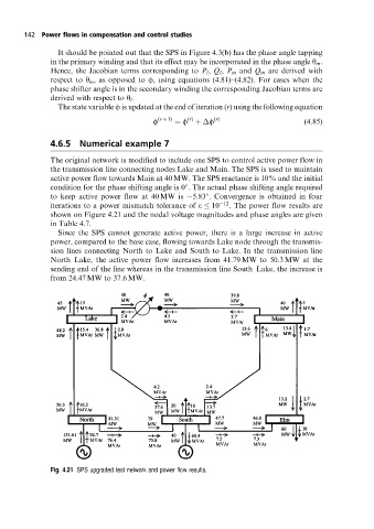
4.6.5 Numerical example 7
The original network is modified to include one SPS to control active power flow in
the transmission line connecting nodes Lake and Main. The SPS is used to maintain
active power flow towards Main at 40 MW. The SPS reactance is 10% and the initial
condition for the phase shifting angle is 0 . The actual phase shifting angle required
to keep active power flow at 40 MW is 5:83 . Convergence is obtained in four
iterations to a power mismatch tolerance of e 10 12 . The power flow results are
shown on Figure 4.21 and the nodal voltage magnitudes and phase angles are given
in Table 4.7.
Since the SPS cannot generate active power, there is a large increase in active
power, compared to the base case, flowing towards Lake node through the transmis-
sion lines connecting North to Lake and South to Lake. In the transmission line
North±Lake, the active power flow increases from 41.79 MW to 50.3 MW at the
sending end of the line whereas in the transmission line South±Lake, the increase is
from 24.47 MW to 37.6 MW.
Fig. 4.21 SPS upgraded test networkand power flow results.