
Page 156 - Power Electronic Control in Electrical Systems
P. 156
//SYS21/F:/PEC/REVISES_10-11-01/075065126-CH004.3D ± 144 ± [106±152/47] 17.11.2001 9:54AM
144 Power flows in compensation and control studies
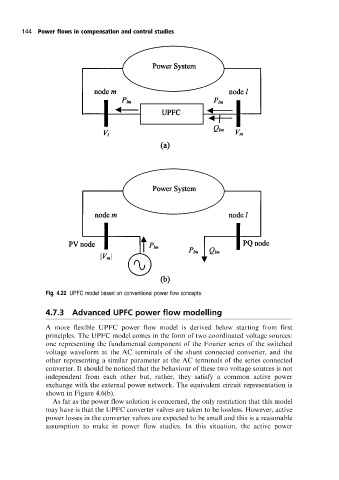
Fig. 4.22 UPFC model based on conventional power flow concepts.
4.7.3 Advanced UPFC power flow modelling
A more flexible UPFC power flow model is derived below starting from first
principles. The UPFC model comes in the form of two coordinated voltage sources:
one representing the fundamental component of the Fourier series of the switched
voltage waveform at the AC terminals of the shunt connected converter, and the
other representing a similar parameter at the AC terminals of the series connected
converter. It should be noticed that the behaviour of these two voltage sources is not
independent from each other but, rather, they satisfy a common active power
exchange with the external power network. The equivalent circuit representation is
shown in Figure 4.6(b).
As far as the power flow solution is concerned, the only restriction that this model
may have is that the UPFC converter valves are taken to be lossless. However, active
power losses in the converter valves are expected to be small and this is a reasonable
assumption to make in power flow studies. In this situation, the active power