
Page 160 - Power Electronic Control in Electrical Systems
P. 160
//SYS21/F:/PEC/REVISES_10-11-01/075065126-CH004.3D ± 148 ± [106±152/47] 17.11.2001 9:54AM
148 Power flows in compensation and control studies
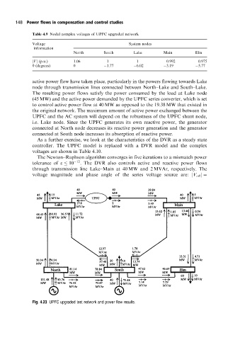
Table 4.9 Nodal complex voltages of UPFC upgraded network
Voltage System nodes
information
North South Lake Main Elm
jVj (p.u.) 1.06 1 1 0.992 0.975
y (degrees) 0 1.77 6.02 3.19 5.77
active power flow have taken place, particularly in the powers flowing towards Lake
node through transmission lines connected between North±Lake and South±Lake.
The resulting power flows satisfy the power consumed by the load at Lake node
(45 MW) and the active power demanded by the UPFC series converter, which is set
to control active power flow at 40 MW as opposed to the 19.38 MW that existed in
the original network. The maximum amount of active power exchanged between the
UPFC and the AC system will depend on the robustness of the UPFC shunt node,
i.e. Lake node. Since the UPFC generates its own reactive power, the generator
connected at North node decreases its reactive power generation and the generator
connected at South node increases its absorption of reactive power.
As a further exercise, we look at the characteristics of the DVR as a steady state
controller. The UPFC model is replaced with a DVR model and the complex
voltages are shown in Table 4.10.
The Newton±Raphson algorithm converges in five iterations to a mismatch power
tolerance of e 10 12 . The DVR also controls active and reactive power flows
through transmission line Lake±Main at 40 MW and 2 MVAr, respectively. The
voltage magnitude and phase angle of the series voltage source are: jV cR j
Fig. 4.23 UPFC upgraded test networkand power flow results.