Page 158 - Power Electronic Control in Electrical Systems
P. 158

//SYS21/F:/PEC/REVISES_10-11-01/075065126-CH004.3D ± 146 ± [106±152/47] 17.11.2001 9:54AM


               146 Power flows in compensation and control studies

                      The active and reactive powers for the series converter are derived as follows:

                            S cR ˆ P cR ‡ jQ cR ˆ V cR I ˆ V cR Y V ‡ Y mm V ‡ Y mm V cR 	  (4:92)


                                                 m
                                                              l
                                                           ml
                                                                      m
                                    2
                                           j
                          P cR ˆ V cR j G mm ‡ V cR kV l j G ml cos (y cR   y l ) ‡ B ml sin (y cR   y l )f  g
                                j
                                                                                        (4:93)
                              ‡ V cR kV m j G mm cos (y cR   y m ) ‡ B mm sin (y cR   y m )g
                                j
                                        f
                                     2
                                            j
                                                   f
                          Q cR ˆ jV cR j B mm ‡ V cR kV l j G ml sin (y cR   y l )   B ml cos (y cR   y l )g
                                                                                        (4:94)
                               j
                             ‡ V cR kV m j G mm sin (y cR   y m )   B mm cos (y cR   y m )g
                                       f
                      The active and reactive powers for the shunt converter are derived as follows


                                    S vR ˆ P vR ‡ jQ vR ˆ V vR I vR  ˆ V vR Y vR  V vR    V l    (4:95)
                                       2
                           P vR ˆ jV vR j G l0 ‡ V vR kV l j G l0 cos (y vR   y l ) ‡ B l0 sin (y vR   y l )  (4:96)
                                            j
                                                    f
                                     2
                           Q vR ˆ V vR j B l0 ‡ V vR kV l j G l0 sin (y vR   y l )   B l0 cos (y vR   y l )g  (4:97)
                                           j
                                                  f
                                 j
                      Assuming lossless converters, the UPFC neither absorbs nor injects active power
                      with respect to the AC system. Hence, the following constraint equation must be
                      satisfied
                                                   P vR ‡ P cR ˆ 0                      (4:98)
                      This is a complex model, which imposes severe demands on the numerical algorithms
                      used for its solution. Since in power systems planning and operation reliability
                      towards the convergence is the main concern, it is recommended that the Newton±
                      Raphson algorithm be used for its solution (Fuerte-Esquivel et al., 2000). In this
                      method the UPFC state variables are combined with the network nodal voltage
                      magnitudes and phase angles in a single frame-of-reference for a unified, iterative
                      solution. The UPFC state variables are adjusted automatically in order to satisfy
                      specified power flows and voltage magnitudes.
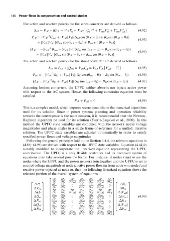
                        Following the general principles laid out in Section 4.4.4, the relevant equations in
                      (4.88)±(4.98) are derived with respect to the UPFC state variables. Equation (4.44) is
                      suitably modified to incorporate the linearized equation representing the UPFC
                      contribution. The UPFC is a very flexible controller and its linearized system of
                      equations may take several possible forms. For instance, if nodes l and m are the
                      nodes where the UPFC and the power network join together and the UPFC is set to
                      control voltage magnitude at node l, active power flowing from node m to node l and
                      reactive power injected at node m, then the following linearized equation shows the
                      relevant portion of the overall system of equations
                                     2                                    3
                                       @P l  @P l  @P l  @P l  @P l  @P l  @P l
                                       @y l  @y m  @jV vR j  @jV m j  @y cR  @jV cR j
                          2      3                                    @y vR 2      3
                             P l     6  @P m  @P m  0  @P m  @P m  @P m   7    y l
                                                                 j
                                     6                                 0 7
                                       @y l  @y m     @jV m j  @y cR  @ V cR j
                          6   P m  7  6                                   76   y m  7
                                       @Q l  @Q l  @Q l  @Q l  @Q l  @Q l
                          6      7   6                                 @Q l 76     7
                                                                              j
                                                       j
                                                                 j
                             Q l       @y l  @y m  @ V vR j  @ V m j  @y cR  @ V cR j  @y vR
                                                 j
                          6      7   6                                    76    V vR j  7
                          6      7   6                                    76       7
                                      @Q m  @Q m      @Q m  @Q m  @Q m
                                                                              j
                             Q m                                       0 76
                          6      7  ˆ  6          0                            V m j  7  (4:99)
                                                       j
                                                                 j
                                       @y l  @y m     @ V m j  @y cR  @ V cR j
                          6      7   6                                    76       7
                                                  0
                          6      7   6  @P ml  @P ml  @P ml  @P ml  @P ml  76      7
                                       @y l  @y m     @ V m j  @y cR  @ V cR j
                          6   P ml 7  6                                0 76   y cR 7
                                                       j
                                                                 j
                                                                              j
                             Q ml
                          4      5   6                                    74    V cR j  5
                                      @Q ml  @Q ml    @Q ml  @Q ml  @Q ml
                                     6            0                    0  7
                                                                 j
                                                       j
                             P bb    4  @y l  @y m    @ V m j  @y cR  @ V cR j  5   y vR
                                      @P bb  @P bb  @P bb  @P bb  @P bb  @P bb  @P bb
                                       @y l  @y m  @ V vR j  @ V m j  @y cR  @ V cR j  @y vR
                                                 j
                                                       j
                                                                 j
   153   154   155   156   157   158   159   160   161   162   163