
Page 134 - Power Electronics Handbook
P. 134
Overvoltage protection 127
Figure 5.4 A ‘crowbar’ circuit for overvoltage protection
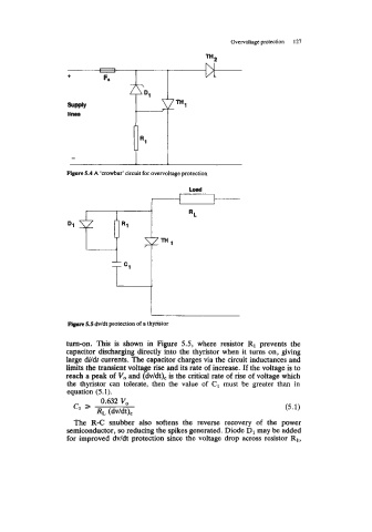
Figure 5.5 dv/dt protection of a thyristor
turn-on. This is shown in Figure 5.5, where resistor R1 prevents the
capacitor discharging directly into the thyristor when it turns on, giving
large dildf currents. The capacitor charges via the circuit inductances and
limits the transient voltage rise and its rate of increase. If the voltage is to
reach a peak of V,, and (dv/dt)= is the critical rate of rise of voltage which
the thyristor can tolerate, then the value of C, must be greater than in
equation (5.1).
0.632 V,
c1 2
RL (dV/dt),
The R-C snubber also softens the reverse recovery of the power
semiconductor, so reducing the spikes generated. Diode D1 may be added
for improved dv/dt protection since the voltage drop across resistor R1,