
Page 135 - Power Electronics Handbook
P. 135
128 Power semiconductor protection
when the capacitor is charging, will be seen by the power semiconductor.
The value of the suppression capacitor and resistor are often empirically
chosen, depending on circuit conditions, with R1 being in the range of
lO-lOOhZ, and C1 in the range 0.1-1 @.
(a) (b) (cJ
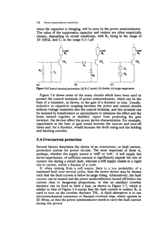
Figure 5.6 Control terminal protection: (a) R-C circuit; (b) diodes; (c) surge suppressors
Figure 5.6 shows some of the many circuits which have been used to
protect the control terminals of power semiconductors, which can be the
base of a transistor, as shown, or the gate of a thyristor or triac. Usually,
inductive or capacitive coupling between the power and control circuits
induces voltage transients into the control terminal, and this terminal can
be isolated by transformers or optoisolators to minimise the effect and the
leads twisted together or shielded. Apart from protecting the gate
terminal, the devices affect the power device characteristics. For example,
capacitance in the base or gate would increase the turn-on and turn-off
times and, for a thyristor, would increase the dv/dt rating and the holding
and latching currents.
5.4 Overcurrent protection
Several factors determine the choice of an overcurrent, or fault current,
protection system for power circuits. The most important of these is,
perhaps, whether the supply source is ‘stiff’ or ‘soft.’ A soft supply has
series impedances, of sufficient amount to significantly impede the rate of
current rise during a circuit fault, whereas a stiff supply results in a rapid
rise in current, within a fraction of a cycle.
If, when running from a soft source, there is a low probability of a
sustained fault over several cycles, then the power device may be chosen
such that the fault current is below its surge rating. Alternatively, the fault
current can be sensed and the power semiconductors turned off before the
current rises to dangerous proportions, or else an auxiliary crowbar
thyristor can be fired to blow a fuse, as shown in Figure 5.7, which is
similar to that of Figure 5.4 except that the fault current in resistor R1 is
used to turn on the crowbar thyristor TH1. A third alternative is to use
electromechanical contactors or thermal overload trips, which operate in
20-80ms, so that the power semiconductor needs to carry the fault current
during this period.