
Page 140 - Power Electronics Handbook
P. 140
Overcurrent protection 133
Power semiconductor
Circuit breaker
Fuse will protect
1 this point
to
I
I
I
1
751100 ms Time
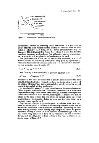
Mlprr 5.11 Characteristics of several protective devices
asymmetrical current by increasing circuit reactances. It is important to
ensure that the fault current reaches a sufficient value to blow the fuse
within a relatively short time, or the power semiconductor may be
damaged. This is illustrated in Figure 5.11, where it is seen that for stiff
supplies a fast-acting semiconductor fuse will protect a power semiconduc-
tor, whereas for soft supplies circuit breakers must be used.
The performance of a fuse can be improved by connecting several of
them in parallel, the total steady state current being given by equation (5.3)
where N is the number of fuses in parallel and F is a factor which accounts
for fuse mismatch, being typically 0.9.
itotal = ionefus X N X F (5 * 3)
The i2t rating of the combination is given by equation (5.4).
(i2t)total = (i2t)onehse x N2 (5.4)
Therefore if two fuses are connected in parallel each is required to have
about half the steady state rating of one fuse, but the i2t rating is improved
by a factor of four. Fuses can be connected in parallel by having several
elements in parallel within a single case.
As mentioned in section 5.2, rapid rates of current increase (dildt) cause
failure in power semiconductors. This current increase is due to low source
impedances during a short circuit, or to discharge of suppression capacitors
or recovery currents of other devices, as in Figure 1.9. Inductances may be
added in the lines to limit the rate of rise of current within the power
semiconductor, the inductors being air cored and therefore linear, or a
saturable reactor may be used.
Fuses are not effective in protecting power transistors, since these may
come out of saturation as the fault current through them increases, due to
insufficient base drive. This would limit the current, preventing the fuse
from blowing quickly, whilst causing high dissipation across the power
transistor, leading to failure. In these instances current sensing is used, the
base drive being removed to turn off the transistor, or else a crowbar
device, such as a thyristor, is fired to blow a line fuse, as shown in the
simple circuit of Figure 5.7.