
Page 145 - Power Electronics Handbook
P. 145
138 Power semiconductor circuits - a r6sum6
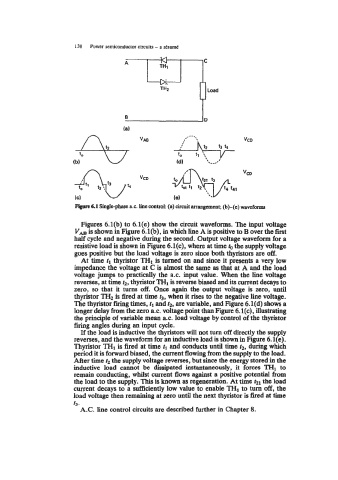
6.1 Single-phase a.c. line control: (a) circuit arrangement; (b)-(e) waveforms
Figures 6.l(b) to 6.l(e) show the circuit waveforms. The input voltage
V, is shown in Figure 6.l(b), in which line A is positive to B over the first
half cycle and negative during the second. Output voltage waveform for a
resistive load is shown in Figure 6.l(c), where at time the supply voltage
goes positive but the load voltage is zero since both thyristors are off.
At time tl thyristor "HI is turned on and since it presents a very low
impedance the voltage at C is almost the same as that at A and the load
voltage jumps to practically the a.c. input value. When the line voltage
reverses, at time t2, thyristor THl is reverse biased and its current decays to
zero, so that it turns off. Once again the output voltage is zero, until
thyristor TH2 is fired at time t3, when it rises to the negative line voltage.
The thyristor firing times, tl and t2, are variable, and Figure 6.l(d) shows a
longer delay from the zero 8.c. voltage point than Figure 6.l(c), illustrating
the principle of variable mean a.c. load voltage by control of the thyristor
firing angles during an input cycle.
If the load is inductive the thyristors will not turn off directly the supply
reverses, and the waveform for an inductive load is shown in Figure 6.l(e).
Thyristor THI is fired at time tl and conducts until time t2, during which
period it is forward biased, the current flowing from the supply to the load.
After time t2 the supply voltage reverses, but since the energy stored in the
inductive load cannot be dissipated instantaneously, it forces TH1 to
remain conducting, whilst current flows against a positive potential from
the load to the supply. This is known as regeneration. At time hl the load
current decays to a sufficiently low value to enable THl to turn off, the
load voltage then remaining at zero until the next thyristor is fired at time
t3.
A.C. line control circuits are described further in Chapter 8.