
Page 150 - Power Electronics Handbook
P. 150
D.C. line control 143
I D
t
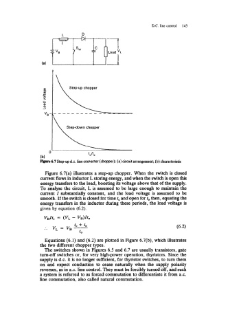
prrvC 6.7 Step-up d.c. Line converter (chopper): (a) circuit arrangement; (b) characteristic
Figure 6.7(a) illustrates a step-up chopper. When the switch is closed
current flows in inductor L storing energy, and when the switch is open this
energy transfers to the load, boosting its voltage above that of the supply.
To analyse the circuit, L is assumed to be large enough to maintain the
current Z substantially constant, and the load voltage is assumed to be
smooth. If the switch is closed for time tc and open for to then, equating the
energy transfers in the inductor during these periods, the load voltage is
given by equation (6.2).
v,ztc = (V, - Vl3)ZCo
Equations (6.1) and (6.2) are plotted in Figure 6.7(b), which illustrates
the two different chopper types.
The switches shown in Figures 6.5 and 6.7 are usually transistors, gate
turn-off switches or, for very high-power operation, thyristors. Since the
supply is d.c. it is no longer sufficient, for thyristor switches, to turn them
on and expect conduction to cease naturally when the supply polarity
reverses, as in a.c. line control. They must be forcibly turned off, and such
a system is referred to as forced commutation to differentiate it from a.c.
line commutation, also called natural commutation.