
Page 149 - Power Electronics Handbook
P. 149
142 Power semiconductor circuits - a &sum&
F@pre 6.5 D.C. line control circuit arrangement (chopper)
When the switch is closed the load voltage is equal to the supply VB, the
voltage drop across the switch being ignored. With the switch open the
voltage is zero if the leakage current through the switch is assumed to be
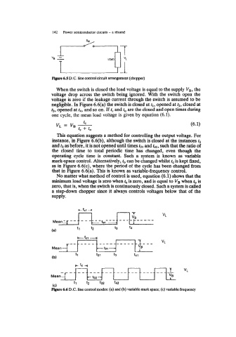
neghgible. In Figure 6.6(a) the switch is closed at tl, opened at t2, closed at
t3, opened at t4, and so on. If tc and to are the closed and open times during
one cycle, the mean load voltage is given by equation (6.1).
This equation suggests a method for controlling the output voltage. For
instance, in Figure 6.6(b), although the switch is closed at the instances tl
and t3 as before, it is not opened until times t21 and t41, such that the ratio of
the closed time to total periodic time has changed, even though the
operating cycle time is constant. Such a system is known as variable
mark-space control. Alternatively, to can be changed whilst tc is kept fixed,
as in Figure 6.6(c), where the period of the cycle has been changed from
that in Figure 6.6(a). This is known as variable-frequency control.
No matter what method of control is used, equation (6.1) shows that the
minimum load voltage is zero when tc is zero, and is equal to VB when to is
zero, that is, when the switch is continuously closed. Such a system is called
a step-down chopper since it always controls voltages below that of the
supply.
ctcr 4
n n-r
tl tz t3 t4
-_ --_.-- -._--_---
Mean - to2-
tl t2 t32 t42
(C)
Ftgmrc 6.6 D.C. line control modes: (a) and (b) variable mark space; (c) variable frequency