
Page 151 - Power Electronics Handbook
P. 151
144 Power semiconductor circuits - a &sum6
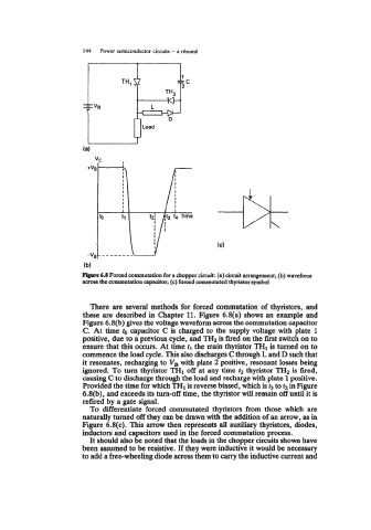
F&lue 6.8 Forced commutation for a chopper circuit: (a) circuit arrangement; (b) waveform
across the commutation capacitor; (c) forced commutated thyristor symbol
There are several methods for forced commutation of thyristors, and
these are described in Chapter 11. Figure 6.8(a) shows an example and
Figure 6.8(b) gives the voltage waveform across the commutation capacitor
C. At time to capacitor C is charged to the supply voltage with plate 1
positive, due to a previous cycle, and THz is fired on the first switch on to
ensure that this om. At time tl the main thyristor TH1 is turned on to
commence the load cycle. This also discharges C through L and D such that
it resonates, recharging to VB with plate 2 positive, resonant losses being
ignored. To turn thyristor TH1 off at any time t2 thyristor TH2 is fired,
causing C to discharge through the load and recharge with plate 1 positive.
Provided the time for which TH1 is reverse biased, which is t3 to t2 in Figure
6.8(b), and exceeds its turn-off time, the thyristor will remain off until it is
refired by a gate signal.
To differentiate forced commutated thyristors from those which are
naturally turned off they can be drawn with the addition of an arrow, as in
Figure 6.8(c). This arrow then represents all auxiliary thyristors, diodes,
inductors and capacitors used in the forced commutation process.
It should also be noted that the loads in the chopper circuits shown have
been assumed to be resistive. If they were inductive it would be necessary
to add a free-wheeling diode across them to carry the inductive current and