
Page 146 - Power Electronics Handbook
P. 146
Conrolled rectification and inversion 139
6.4 Controlled rectif‘ication and inversion
Power rectifiers are used where rectification of an a.c. supply to a d.c. load
is required, although these devices cannot be controlled in relation to their
turn-on point in an a.c. cycle. Where this control is required thyristors are
almost invariably used due to their unidirectional conduction properties,
and a typical circuit is shown in Figure 6.2, where the load is assumed to be
resistive, or inductive with a free-wheeling diode connected.
(C) (d)
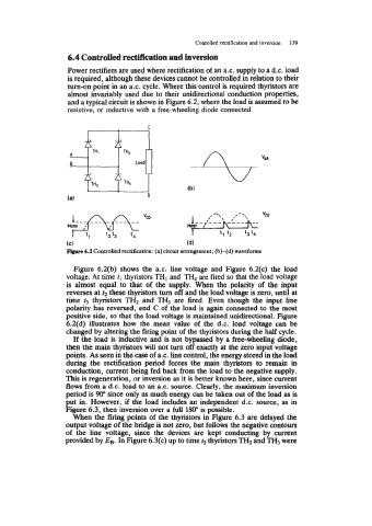
Fipurr 6.2 Controlled rectification: (a) circuit arrangement; (b)-(d) waveforms
Figure 6.2(b) shows the a.c. line voltage and Figure 6.2(c) the load
voltage. At time fl thyristors TH, and TH, are fired so that the load voltage
is almost equal to that of the supply. When the polarity of the input
reverses at t2 these thyristors turn off and the load voltage is zero, until at
time f3 thyristors TH2 and TH3 are fired. Even though the input line
polarity has reversed, end C of the load is again connected to the most
positive side, so that the load voltage is maintained unidirectional. Figure
6.2(d) illustrates bow the mean value of the d.c. load voltage can be
changed by altering the firing point of the thyristors during the half cycle.
If the load is inductive and is not bypassed by a free-wheeling diode,
then the main thyristors will not turn off exactly at the zero input voltage
points. As seen in the case of a.c. line control, the energy stored in the load
during the rectification period forces the main thyristors to remain in
conduction, current being fed back from the load to the negative supply.
This is regeneration, or inversion as it is better known here, since current
flows from a d.c. load to an a.c. source. Clearly, the maximum inversion
period is 90” since only as much energy can be taken out of the load as is
put in. However, if the load includes an independent d.c. source, as in
Figure 6.3, then inversion over a full 180” is possible.
When the firing points of the thyristors in Figure 6.3 are delayed the
output voltage of the bridge is not zero, but follows the negative contours
of the line voltage, since the devices are kept conducting by current
provided by EB. In Figure 6.3(c) up to time t2 thyristors TH2 and TH3 were