
Page 136 - Power Electronics Handbook
P. 136
Overcurrent protection 129
Fu- FS1
I I
LOAD
THl
\ N RL
-
A
R
1
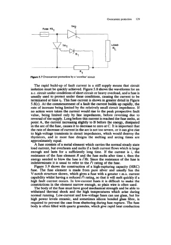
5.7 Overcurrent protection by a ‘crowbar’ circuit
The rapid build-up of fault current in a stiff supply means that circuit
isolation must be quickly achieved. Figure 5.8 shows the waveforms for an
a.c. circuit under conditions of short circuit or heavy overload, and a fuse is
usually used to protect under these conditions, causing the current to be
terminated at time f2. This fuse current is shown in greater detail in Figure
5.8(c). At the commencement of a fault the current builds up rapidly, the
rate of increase being limited by the relatively small circuit impedance. If
no action were taken the current would rise to the peak prospective fault
value, being limited only by line impedances, before reversing due to
reversal of the supply. Long before this current is reached the fuse melts, at
point A, the current increasing slightly to B before the energy, dissipated
in the arc of the fuse, causes it to decrease to zero at C. It is important that
the rate of decrease of current in the arc is not too severe, or it can give rise
to high-voltage transients in circuit impedances, which would destroy the
thyristors, and in most fuse designs the melting and arcing times are
approximately equal.
A fuse consists of a metal element which cames the normal steady state
load current, but overheats and melts if a fault current flows which is large
enough and lasts for a sufficiently long time. If the current is i, the
resistance of the fuse element R and the fuse melts after time f, then the
energy needed to blow the fuse is i2Rt. Since the resistance of the fuse is
indeterminate it is usual to refer to the i2f rating of the fuse.
Figure 5.9 shows the construction of a high-rupturing capacity (HRC)
fuse. The fuse element is made from pure silver and usually has the
V-notch structure shown, which gives a fuse with a greater r.m.s. current
capability whilst having a reduced i2t rating, so that it will melt quickly if a
high fault current occurs. In low-current fuses it is difficult to make the
constrictions in the element narrow enough, so plain wire is often used.
The body of the fuse! must have good mechanical strength and be able to
withstand thermal shock and the high temperatures which arise during
normal running. Low-current and low-voltage fuses can use glass, but for
high power levels ceramic, and sometimes silicon bonded glass fibre, is
required to prevent the case from shattering during fuse rupture. The fuse
body is often filled with quartz granules, which give rapid heat conduction