
Page 22 - Power Electronics Handbook
P. 22
Power recrifier principles 15
minority carriers in the p and n regions, respectively; then the reverse
current density for diffusion-limited operation is given by equation
(1.2), assuming that the p and n regions are short compared to the
minority carrier diffusion length. In this equation Dp and Do are the
hole and electron diffusion constants, respectively.
(iii) Charge generation within the depletion layer. This is generally the
cause of most of the leakage current, and its value is given by
equation (1.3), where ZIr is the space charge generated leakage
current in A per square centimetre; q is the charge on an electron; ne
is the intrinsic electron concentration; W, is the width of the
depletion layer; and r, is the space charge generation lifetime.
The current therefore varies directly as the volume of the depletion layer
and inversely as the space charge generation lifetime. High-voltage
junctions have wide depletion layers, so it is important to have long
lifetimes during processing. The charge generation is proportional to ne so
it doubles for approximately every ll°C rise in temperature.
1.3.3 Modifled structures
In order to reduce the surface currents, and improve the breakdown
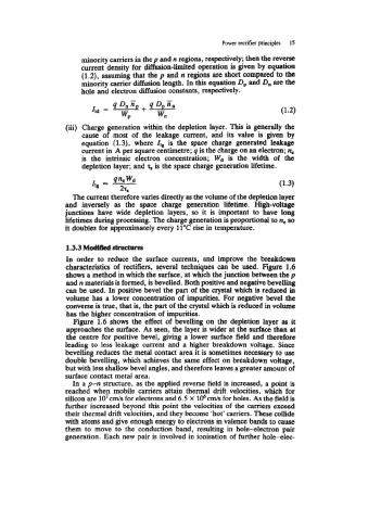
characteristics of rectifiers, several techniques can be used. Figure 1.6
shows a method in which the surface, at which the junction between the p
and n materials is formed, is bevelled. Both positive and negative bevelling
can be used. In positive bevel the part of the crystal which is reduced in
volume has a lower concentration of impurities. For negative bevel the
converse is true, that is, the part of the crystal which is reduced in volume
has the higher concentration of impurities.
Fwre 1.6 shows the effect of bevelling on the depletion layer as it
approaches the surface. As seen, the layer is wider at the surface than at
the centre for positive bevel, giving a lower surface field and therefore
leading to less leakage current and a higher breakdown voltage. Since
bevelling reduces the metal contact area it is sometimes necessary to use
double bevelling, which achieves the same effect on breakdown voltage,
but with less shallow bevel angles, and therefore leaves a greater amount of
surface contact metal area,
In a p-n structure, as the applied reverse field is increased, a point is
reached when mobile carriers attain thermal drift velocities, which for
silicon are lo7 cm/s for electrons and 6.5 X 106 cm/s for holes. As the field is
further increased beyond this point the velocities of the carriers exceed
their thermal drift velocities, and they become 'hot' carriers. These collide
with atoms and give enough energy to electrons in valence bands to cause
them to move to the conduction band, resulting in hole-electron pair
generation. Each new pair is involved in ionisation of further hole-elec-