
Page 57 - Power Quality in Electrical Systems
P. 57
40 Chapter Three
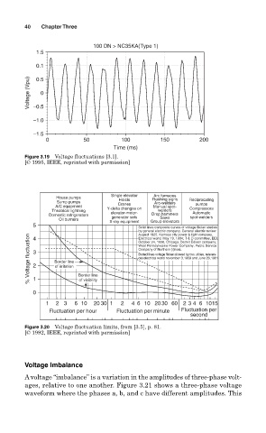
100 DN > NC35KA(Type 1)
1.5
0.1
Voltage (Vpu) −0.5 0
0.5
−1.0
−1.5
0 50 100 150 200
Time (ms)
Figure 3.19 Voltage fluctuations [3.1].
[© 1995, IEEE, reprinted with permission]
Single elevator Arc furnaces
House pumps Hoists Flashing signs Reciprocating
Sump pumps Arc-welders
A/C equipment Cranes Manual spot- pumps
Theatrical lightning Y-delta changes on welders Compressors
Automatic
Domestic refrigerators elevator-motor- Drop hammers spot-welders
generator sets
Saws
Oil burners X-ray equipment Group elevators
5
Solid lines composite curves of voltage flicker studies
by general electric company. General electric review
August 1925; Kamsas city power & light company,
% Voltage fluctuation 3 2 Border line Border line West Pennsytwanie Power Company; Public Service
4
Electrical world. May 19, 1934; T & D committee, EEI.
October 24, 1936. Chicago; Detrcit Edison company;
Company of Northern [i]inois.
Dotted lines voltage flicker allowed by two utlities, referen-
ces electrical world november 3, 1959 and June 26, 1961
of irritation
0 1 of visibility
1 2 3 6 10 20 30 1 2 4 6 10 20 30 60 2 3 4 6 1015
Fluctuation per hour Fluctuation per minute Fluctuation per
second
Figure 3.20 Voltage fluctuation limits, from [3.5], p. 81.
[© 1992, IEEE, reprinted with permission]
Voltage Imbalance
Avoltage “imbalance” is a variation in the amplitudes of three-phase volt-
ages, relative to one another. Figure 3.21 shows a three-phase voltage
waveform where the phases a, b, and c have different amplitudes. This