
Page 54 - Power Quality in Electrical Systems
P. 54
Voltage Distortion 37
Vout+
D1 D2
I L
+
−
v s
200 A
D3 D4 Vout−
(a)
300 V
250 V
200 V
150 V
100 V
50 V
0 V
−50 V
0 s 2 ms 4 ms 6 ms 8 ms 10 ms 12 ms 14 ms 16 ms 18 ms 20 ms
Time
(b)
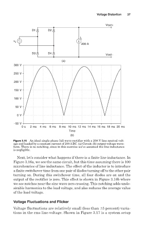
Figure 3.15 An ideal single-phase full-wave rectifier with a 208-V line-neutral volt-
age and loaded by a constant current of 200 A DC. (a) Circuit; (b) output voltage wave-
form. There is no notching, since in this exercise we’ve assumed the line inductance
is negligible.
Next, let’s consider what happens if there is a finite line inductance. In
Figure 3.16a, we see the same circuit, but this time assuming there is 100
microhenries of line inductance. The effect of the inductor is to introduce
a finite switchover time from one pair of diodes turning off to the other pair
turning on. During this switchover time, all four diodes are on and the
output of the rectifier is zero. This effect is shown in Figure 3.16b where
we see notches near the sine wave zero crossing. This notching adds unde-
sirable harmonics to the load voltage, and also reduces the average value
of the load voltage.
Voltage Fluctuations and Flicker
Voltage fluctuations are relatively small (less than 5 percent) varia-
tions in the rms line-voltage. Shown in Figure 3.17 is a system setup