
Page 49 - Power Quality in Electrical Systems
P. 49
32 Chapter Three
impedance from Example 3.2. Note that the line impedance is 0.002
j0.01 . At high frequencies, the line impedance is dominated by the line
inductance. In this case, the inductance is
X L X L 0.01
L 5 5 5 5 26.5 µH
2pf 2ps60d 2ps60d
We’ll approximate the negative rising edge of the lightning strike as
rising to –23 kiloamperes in 5 microseconds. The lightning strike then
decays to zero in approximately 100 microseconds. Using these assump-
tions, and remembering that v Ldi/dt and ignoring the voltage drop
across the resistor, we find
223,000
26
v 5 s26.5 3 10 da 26 b 52121.9 kV
1
5 3 10
23,000
26
v 5 s26.5 3 10 da 26 b 516.1 kV
2
100 3 10
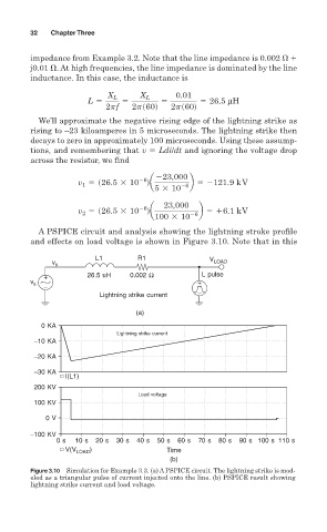
A PSPICE circuit and analysis showing the lightning stroke profile
and effects on load voltage is shown in Figure 3.10. Note that in this
L1 R1 V
v s LOAD
+ 26.5 uH 0.002 Ω L pulse
v +
−
s
Lightning strike current −
(a)
0 KA
Lightning strike current
−10 KA
−20 KA
−30 KA
I(L1)
200 KV
Load voltage
100 KV
0 V
−100 KV
0 s 10 s 20 s 30 s 40 s 50 s 60 s 70 s 80 s 90 s 100 s 110 s
V(V LOAD ) Time
(b)
Figure 3.10 Simulation for Example 3.3. (a) A PSPICE circuit. The lightning strike is mod-
eled as a triangular pulse of current injected onto the line. (b) PSPICE result showing
lightning strike current and load voltage.