
Page 56 - Power Quality in Electrical Systems
P. 56
Voltage Distortion 39
External
R + jX
sources
External
Capacitor
sources
+ banks
− Residences: Welders Rolling Residences
Internal
A.C.s sources mills
dryer Lamps
washers
Figure 3.17 A circuit capable of flicker propagation to a residence [3.4].
[© 2004, IEEE, reprinted with permission]
that can cause voltage variations. A varying source of harmonic cur-
rents includes welders and capacitor banks. Voltage variation created
by this setup couples to residential lighting through the distribution
system.
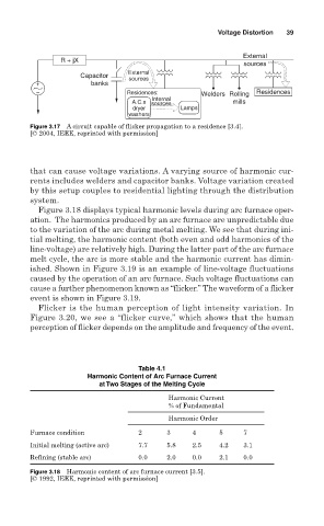
Figure 3.18 displays typical harmonic levels during arc furnace oper-
ation. The harmonics produced by an arc furnace are unpredictable due
to the variation of the arc during metal melting. We see that during ini-
tial melting, the harmonic content (both even and odd harmonics of the
line-voltage) are relatively high. During the latter part of the arc furnace
melt cycle, the arc is more stable and the harmonic current has dimin-
ished. Shown in Figure 3.19 is an example of line-voltage fluctuations
caused by the operation of an arc furnace. Such voltage fluctuations can
cause a further phenomenon known as “flicker.” The waveform of a flicker
event is shown in Figure 3.19.
Flicker is the human perception of light intensity variation. In
Figure 3.20, we see a “flicker curve,” which shows that the human
perception of flicker depends on the amplitude and frequency of the event.
Table 4.1
Harmonic Content of Arc Furnace Current
at Two Stages of the Melting Cycle
Harmonic Current
% of Fundamental
Harmonic Order
Furnace condition 2 3 4 5 7
Initial melting (active arc) 7.7 5.8 2.5 4.2 3.1
Refining (stable arc) 0.0 2.0 0.0 2.1 0.0
Figure 3.18 Harmonic content of arc furnace current [3.5].
[© 1992, IEEE, reprinted with permission]