
Page 102 - Practical Control Engineering a Guide for Engineers, Managers, and Practitioners
P. 102
A New Do11ain and lore Process Models 11
Equation (4-1) shows that, when the output flow rate is the pro-
cess output and the input flow rate is the process input, the process
gain is unity and the time constant is the same as when the level is
the process output. Making this choice of process input and output
variables will simplify some of the graphs and some of the interpre-
tations. Later on, we can extend the presentation to nonunity gains
with ease.
Now, with this simple background in mind, what will the output
flow rate look like when the input flow rate oscillates about some
nominal value? First, F will have a nominal value Fe and it will vary
0
about its nominal value with an amplitude, AY' a frequency, f, and a
phase (relative to that ofF;), 8, as in
(4-2)
Note that the frequency of the oscillations in the input flow
rate and the tank level is the same. This is an assumption that we
will support soon. However, the amplitudes and the phases are
different.
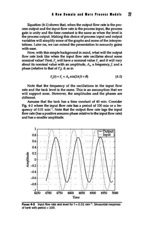
Assume that the tank has a time constant of 40 min. Consider
Fig. 4-2 where the input flow rate has a period of 100 min or a fre-
1
quency of 0.01 min- • Note that the output flow rate lags the input
flow rate (has a positive nonzero phase relative to the input flow rate)
and has a smaller amplitude.
1
0.8
0.6
0.4
., 0.2
Q.l
.a
=a 0
~ -0.2
-0.4
-0.6
-0.8
-1
4650 4700 4750 4800 4850 4900 4950 5000
Time
1
F1auRE 4-2 Input flow rate and level for f = 0.01 min- • Sinusoidal response
of tank with period = 100.