
Page 155 - Practical Control Engineering a Guide for Engineers, Managers, and Practitioners
P. 155
130 Chapter Five
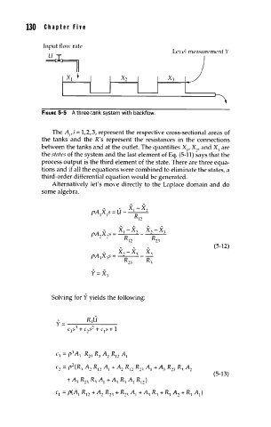
FIGURE 5-5 A three-tank system with backflow.
The A ,i = 1,2,3, represent the respective cross-sectional areas of
1
the tanks and the R's represent the resistances in the connections
betvveen the tanks and at the outlet. The quantities X , X:-!, and X, are
1
the states of the system and the last element of Eq. (5-11) says that the
process output is the third element of the state. There are three equa-
tions and if all the equations were combined to eliminate the states, a
third-order differential equation would be generated.
Alternati\'ely let's mo\·e directly to the Laplace domain and do
some algebra.
- - XI- X.,
('A X "=U -----
1 I" Rl:-!
(5-12)
Soh·ing for Y yields the following:
c, =(''A, R:-!, R,, A:-! R1:-! AI
c:-! = (':-!(R, A:-! R 1 :-! A 1 +A:-! R 1 :-! R:-!, A + AJ R:-! 3 R, A:-!
1
(5-13)
+A, R::!., R, AI +A, R, AI Rl::!.)
c.= ('(AI Rl::!. +A::!. R::!., + R::!., AI+ A, R, + R, A::!.+ R, AI)