
Page 551 - Practical Design Ships and Floating Structures
P. 551
526
All of the symbols are used accordiig to the ISOlDIS 15016 and ITTC standard symbols.
2 SPEED TRIAL ANALYSIS PROCEDURE OF ISO/DIS 15016
The analysis procedure of ISO/DIS 15016 is divided into six steps. This analysis procedure is based on
Taniguchi-Tamura’s Method (Taniguchi etc., 1966). Various calculation methods of resistance
increase due to the disturbances and the deviations are suggested to use at annex of ISODIS 16016. In
this guideline, it has described that the methods presented in the annexes are the latest one available
today, other scientifically-based method including model tests may be adopted as agreed between
shipyard and ship owner.
Calculation of resistance increase due to waves is divided into two stages. One is pre-calculation of
response function of added resistance in regular waves prior to speed trials. The other is main
calculation to be made on board for particular irregular waves during trials. When both seas and swell
are observed and are to be taken into account, the tot4 resistance increase is given by the sum of
resistance increase due to seas and swell calculated independently. The calculation of resistance
increase due to waves is based on Maruo’s formula (Maruo, 1960). In short waves, diffraction of
incident waves is observed around the bow, and this causes the main resistance in waves. As the
correction of this effect, Faltinsen’s formula (Faltinsen etc., 1980), Kwon’s formula (Kwon, 1982) and
Fujii-Takahashi’s formula (Fujii etc., 1975) are suggested to use. For the resistance increase due to
waves, the Townsin-Kwon’s method (Townsin etc., 1993) is suggested to use also. When the
calculation of resistance increase of ships in irregular waves, ITTC standard spectrum and JONS WAP
spectrum are respectively used for the frequency distribution of incident waves for seas and swell.
The analysis method of resistance increase due to wind is suggested to use. The wind resistance
coefficients should be based on data which is derived from model tests in wind tunnel or test resuits of
similar ship. The formula for resistance increase due to steering required by come keeping and the
formula of resistance increase due to drifting are suggested to use. For speed loss due to shallow water,
the Lackenby’s formula (Lackenby, 1963) is suggested to use also.
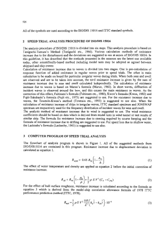
3 COMPUTER PROGRAM OF SPEED TRIAL ANALYSIS
The flowchart of analysis program is shown in Figure 1. All of the suggested methods from
ISO/DIS15016 are contained in this program. Resistance increase due to displacement deviation is
calculated as equation 1.
i 3
R,, = 0.65 R, 1-0
The effect of water temperature and density are applied as equation 2 before the initial correction of
resistance increase.
i 3:
R, = R, 1-- +-p S V2 (C, -C,,)
. -.
For the effect of hull surface roughness, resistance increase is calculated according to the formula as
equation 3 which is derived from the model-ship correlation allowance formula of 1978 ITTC
performance prediction method (ITTC, 1978).
R, =-pS V2 E(k,f -k,,f) .lo-’ (3)
1
2 L3