
Page 202 - Practical Design Ships and Floating Structures
P. 202
1 I1
A WSD provides a long-term wave description for only one specific region. To assess the fatigue
damage on past route services, additional wave information along the routes is necessary. For this
purpose, a global wave database can be used, from which wave data for any wave zone on the service
route can be retrieved.
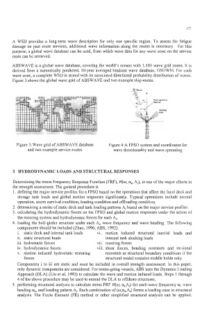
ABSWAVE is a global wave database, covering the world’s oceans with 1,103 wave grid zones. It is
derived from a numerically predicted, 1 0-year averaged hindcast wave database, GSOWM. For each
wave zone, a complete WSD is stored with its associated directional probability distribution of waves.
Figure 3 shows the global wave grid of ABSWAVE and two example ship routes.
Figure 3: Wave grid of ABSWAVE database Figure 4:A FPSO system and coordinates for
and two example service routes wave directionality and wave spreading
3 HYDRODYNAMIC LOADS AND STRUCTURAL RESPONSES
Determining the stress Frequency Response Function (FRF), H(o; a,, A/), is one of the major efforts in
the strength assessment. The general procedure is
1. defining the major service profiles for a FPSO based on the operations that affect the local deck and
storage tank loads and global motion responses significantly. Typical operations include normal
operation, storm survival condition, loading condition and offloading condition.
2. determining a series of static deck and tank loading patterns A, based on the major service profiles.
3. calculating the hydrodynamic forces on the FPSO and global motion responses under the action of
the mooring system and hydrodynamic forces for each A/,
4. loading the hull-girder structure under each A,, wave frequency and wave heading. The following
components should be included (Zhao, 1996; ABS, 1992):
i. static deck and internal tank loads vi. motion induced structural inertial loads and
ii. static structural loads internal tank sloshing loads
iii. hydrostatic forces vii. mooring forces
iv. hydrodynamic forces viii. shear forces, bending moments and torsional
v. motion induced hydrostatic restoring moments as structural boundary conditions if the
forces structural model contains middle holds only.
Components i to iii are static and must be included in overall strength assessment. In this paper,
only dynamic components are considered. For ocean-going vessels, ABS uses the Dynamic Loading
Approach (DLA) (Liu et al, 1992) to calculate the wave and motion induced loads. Steps 1 through
4 of the above procedure may be used to extend the DLA to offshore structures.
5. performing structural analysis to calculate stress FRF H(o; a&) for each wave frequency o, wave
heading a,, and loading pattern A,. Each combination of (o;a,,A,) forms a loading case in structural
analysis. The Finite Element (FE) method or other simplified structural analysis can be applied,