
Page 329 - Practical Design Ships and Floating Structures
P. 329
304
Figure 3. Example of Definition of Principal Particular and Criteria for Stability Assessment
surface model as some geometry production information such as piece, material information, etc., is
necessary at production job.
Recently, however, there has been research on constructing a product model itself in the initial design
stage for integrated design process.
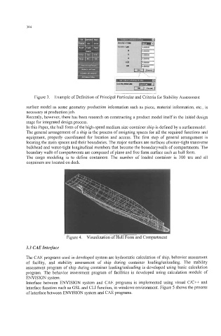
In this Paper, the hull form of the high-speed medium size container ship is defined by a surfacemodel.
The general arrangement of a ship is the process of assigning spaces for all the required functions and
equipment, properly coordinated for location and access. The first step of general arrangement is
locating the main spaces and their boundaries. The major surfaces are surfaces ofwater-tight transverse
bulkhead and water-tight longitudinal members that become the boundarywalls of compartments. The
boundary walls of compartments are composed of plane and free form surface such as hull form.
The cargo modeling is to define containers. The number of loaded container is 300 teu and all
containers are located on deck.
3.3 CAE Interface
The CAE programs used in developed system are hydrostatic calculation of ship, behavior assessment
of facility, and stability assessment of ship during container loadinghloading. The stability
assessment program of ship during container loadinghloading is developed using basic calculation
program. The behavior assessment program of facilities is developed using calculation module of
ENVISION system.
Interface between ENVISION system and CAE programs is implemented using visual C/C++ and
interface function such as GSL and CLI function, in windows environment. Figure 5 shows the process
of interface between ENVISION system and CAE programs.