
Page 328 - Practical Design Ships and Floating Structures
P. 328
303
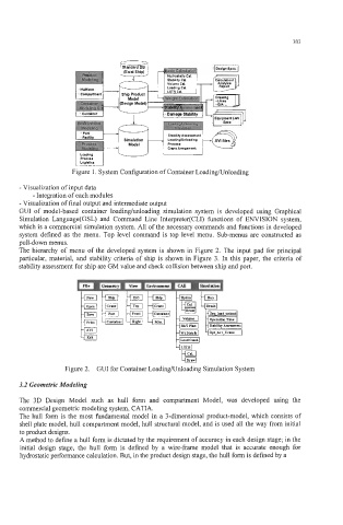
Figure 1. System Configuration of Container LoadingKJnloading
- Visualization of input data
- Integration of each modules
- Visualization of final output and intermediate output
GUI of model-based container loadinghloading simulation system is developed using Graphical
Simulation Language(GSL) and Command Line Interpreter(CL1) functions of ENVISION system,
which is a commercial simulation system. All of the necessary commands and functions in developed
system defined as the menu. Top level command is top level menu. Sub-menus are constructed as
pull-down menus.
The hierarchy of menu of the developed system is shown in Figure 2. The input pad for principal
particular, material, and stability criteria of ship is shown in Figure 3. In this paper, the criteria of
stability assessment for ship are GM value and check collision between ship and port.
Figure 2. GUI for Containei : LoadingKJnloading Simulation System
3.2 Geometric Modeling
The 3D Design Model such as hull form and compartment Model, was developed using the
commercial geometric modeling system, CATIA.
The hull form is the most fundamental model in a 3-dimensional product-model, which consists of
shell plate model, hull compartment model, hull structural model, and is used all the way from initial
to product designs.
A method to define a hull form is dictated by the requirement of accuracy in each design stage; in the
initial design stage, the hull form is defined by a wire-frame model that is accurate enough for
hydrostatic performance calculation. But, in the product design stage, the hull form is defined by a