
Page 360 - Practical Design Ships and Floating Structures
P. 360
335
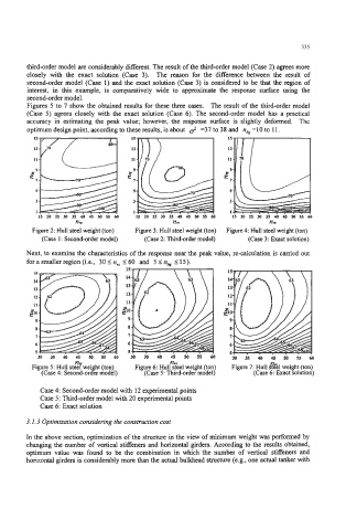
third-order model are considerably different. The result of the thii-order model (Case 2) agrees more
closely with the exact solution (Case 3). The reason for the difference between the result of
second-order model (Case 1) and the exact solution (Case 3) is considered to be that the region of
interest, in this example, is comparatively wide to approximate the response surface using the
second-order model.
Figures 5 to 7 show the obtained results for these three cases. The result of the third-order model
(Case 5) agrees closely with the exact solution (Case 6). The second-order model has a practical
accuracy in estimating the peak value; however, the response surface is slightly deformed. The
optimum design point, according to these results, is about 2 =37 to 38 and nhg =I 0 to 1 1.
15
13
11
P9
=,
s
3
1
15 20 25 30 35 40 45 50 55
nu. nH n,
Figure 2: Hull steel weight (ton) Figure 3: Hull steel weight (ton) Figure 4 Hull steel weight (ton)
(Case 1 : Second-order model) (Case 2: Thirdarder model) (Case 3: Exact solution)
Next, to examine the characteristics of the response near the peak value, re-calculation is carried out
for a smaller region (Le., 30 I nvr I60 and 5 Ink 5 15).
. . . . .
n n, -30 35 40 45 50 55 60
Figure 5: Hull steerwei t (ton) Figure 6: Hull steel weight (ton) Figure 7: Hull #&I weight (ton)
(Case 4: Secondarg model) (Case 5: Third-order model) (Case 6: Exact solution)
Case 4: Second-order model with 12 experimental points
Case 5: Third-order model with 20 experimental points
Case 6: Exact solution
3.1.3 Optimization considering the construction cost
In the above section, optimization of the structure in the view of minimum weight was performed by
changing the number of vertical stiffeners and horizontal girders. According to the results obtained,
optimum value was found to be the combination in which the number of vertical stiffeners and
horizontal girders is considerably more than the actual bulkhead structure (e.g., one actual tanker with