
Page 362 - Practical Design Ships and Floating Structures
P. 362
337
number of horizontal girder is fixed as three. The loading condition is assumed to be the same as that
in the first example shown in 3.1, i.e., full load water pressure on the transverse bulkhead. However,
unlike the first example, for the sake of simplicity the plate thickness of all structures, dimensions, and
the numbers of horizontal girders and vertical stiffeners, and the positions of vertical stiffeners are
assumed to be constants. Therefore, only the intervals of three horizontal girders (Le., xl , x2, xg , x4 )
are assumed to be design variables. Here, x4 is a dependent variable (Le., x4 = tank
depth- xI - x2 - x3 ). A second-order model is utilized to approximate the response as:
Y =PO +PIXI +P2'2 +P3x3 +P4xIxI +P5x2x1 +P6x2x2 +P7'3'I +P8x3x2 +P9x3x3 (lo)
The combinations of design variables chosen by the D-optimal criterion are shown in Table 2.
Twenty FEM models that correspond to the experimental points, presented in Table 2, were prepared,
and the finite element analyses were performed using MSCMASTRAN. As examples of the
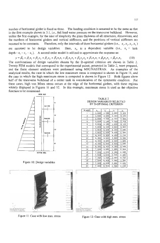
analytical results, the case in which the low maximum stress is computed is shown in Figure 11, and
the case in which the high maximum stress is computed is shown in Figure 12. Both figures show
half of the transverse bulkhead of a center tank in consideration of the symmetric condition. For
these cases, high von Mises stress occurs at the edge of the horizontal girders, with these regions
whitely displayed in Figures 11 and 12. In this example, maximum stress is used as the objective
function to be minimized.
mm
TABLE 2
DESIGN VARIABLES SELECTED
n
BY D-OPTIMAL CRITERION
CIHOIR
+ ...... 2..
a
tdnm
f .__._.
1..
a
ldHOIR
f ...... ?..
%4
- . .
..
.
.
BorxMamL
Figure 10: Design variables
.
'"" me. I..Y~"U""I .... I
0"
Figure 11 : Case with low ma. stress Figure 12: Case with high max. stress