Page 289 - Practical Power System and Protective Relays Commissioning
P. 289

Protection Relays Settings Chapter | 19  283


                I F 5 13,856 A
                I S 5 800 A

                                         13; 856
                                   PSM 5        5 17:32
                                           800
                Using a standard inverse curve of the relay then we have the relay
             operating time T R :
                                       0:14        0:14
                                T R 5    0:0221  5  0:0221
                                     PSM        17:32
                T R 5 2.385
                Assuming that the relay should operates on 1 second then we have:
                t.operation 5 TM.T R
                Where TM 5 time multiplier
                                           1
                                    TM 5       5 0:419
                                         2:385
                Relay (A) setting:
                I set 5 800 A (Primary)
                I set secondary 5 0.5 A
                PSM 5 17
                TM 5 0.4
                Operating time for a fault at end B will be:

                                                   0:14
                                 t:operation 5 0:4 3  0:0221
                                                 17
                t.operation 5 0.96 seconds


             19.1.3 TRANSFORMER OVERCURRENT PROTECTION

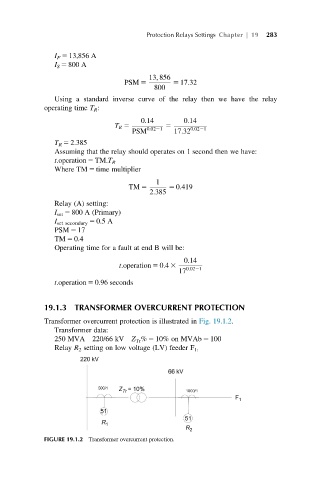
             Transformer overcurrent protection is illustrated in Fig. 19.1.2.
                Transformer data:
                250 MVA   220/66 kV  Z Tr % 5 10% on MVAb 5 100
                Relay R 2 setting on low voltage (LV) feeder F 1:


             FIGURE 19.1.2 Transformer overcurrent protection.
   284   285   286   287   288   289   290   291   292   293   294