
Page 42 - Practical Power System and Protective Relays Commissioning
P. 42
38 Practical Power System and Protective Relays Commissioning
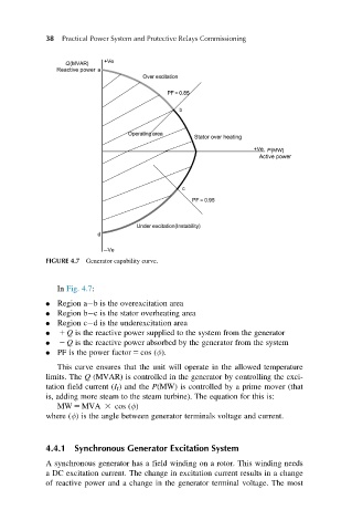
FIGURE 4.7 Generator capability curve.
In Fig. 4.7:
Region a b is the overexcitation area
Region b c is the stator overheating area
Region c d is the underexcitation area
1 Q is the reactive power supplied to the system from the generator
2 Q is the reactive power absorbed by the generator from the system
PF is the power factor 5 cos (φ).
This curve ensures that the unit will operate in the allowed temperature
limits. The Q (MVAR) is controlled in the generator by controlling the exci-
tation field current (I f ) and the P(MW) is controlled by a prime mover (that
is, adding more steam to the steam turbine). The equation for this is:
MW 5 MVA 3 cos (φ)
where (φ) is the angle between generator terminals voltage and current.
4.4.1 Synchronous Generator Excitation System
A synchronous generator has a field winding on a rotor. This winding needs
a DC excitation current. The change in excitation current results in a change
of reactive power and a change in the generator terminal voltage. The most