
Page 106 - Pressure Swing Adsorption
P. 106
L
!LI
80
PRESSURE SWING ADSORPTION PSA CYCLES: BASIC PRINCIPLES 81
Ah:er connected to the inict of bed I. The cvcle configuration 1s summarized m
cooler Figure 3.11.
Water The idea of product reoressunzat1on was put forward for the first tune m a
separa1or very similar oateni for hydrogen puriticauon by Wagner. 14 Prcssunzat10n
Cooling
wa!er with product oushes the residual adsorbed components toward the feed end
Water
of-the adsorber, therchy enhancing the product punty. The four-hed config-
uratton allows continuous product withdrawai and eli"m1nates the use of an
empty tank for storing purge gas.
In multiple-bed systems greater conservation of energy and separative
work are achieved at the cost of a more complex process scheme. In some
Product oxyge11
large-scale hydrogen ourificat1on PSA systems uo to twelve adsorbem beds
are used.
I
,,.-~-, Vaoonzer I I
I I 3.2.4 Vacuum Swmg Cyde
Adsorber Adsorber Adsorber 1 Adsotber I
2 3 I 4 I
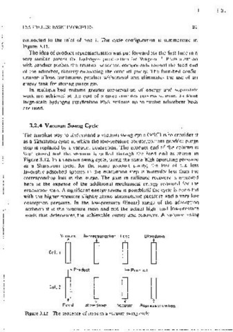
LiQUld I I The simplest way to understand a vacuum swmg cyctdVSC) IS to consider It
oxygen I I as a Skarstrom cycle m which the low-pressure countercurrent orodllct purge
storage I I
L_, _ _j step 1s replaced by a vacuum desorot1on. The oroduct end of the column is
t-'-z kept closed and the vacuum 1s pulled through the feed end· as shown m
Figure 3.12. In a vacuum swmg cycle, usmg the same high operating pressure
Waste n1trocien as a Skarstrom cycie, for the same product punty; the loss of the less
---1--.J
favorahly adsorbed species m the evacuation step 1s ·normally less than the
corresponding loss m the purge. The gatn Jf'l raffinate rccovcrv 1s achieved
Figure 3.10 Schematic diagram of a three~ or four~bed PSA svsiem for air separa~
t1on. (From Ref. 11; rconnted with perm1ss1on.) here at the exoense of the additional mechanical energy reQU1red for the
evacuatton steo. A significant energy savmg 1s oossible:if the cycle is operated
with the higher pressure slightly above atrnosohenc pressure and a verv low
desorption pressure. In the low~oressure (linear) range of the adsorption
isotherm it 1s the pressure ratio and not the actual high- and Jaw-pressure
Vessel
Number levels that determines the achievable ounty and recoverv. A vacuum swmg
I
Adsorption EQI CD I EQ2 CD Purge I EQ2 EQI R
t t t -1, -1, -1, -1, J, 1
2 CD Purge EQ2 EQI R Adsorption EQI CD I EQ2
.j, .j, .j, .j, .j, eo, :·~·· •o•~"-"· "~ "'□--·
t t t
EQI CD EQ2 CD Purge I EQ2 EQI R Adsorpuon
1' t 1' .j, -l, .j, -l, .j,
4 EQI R Adsorpuon EQI CD i EQ2 CD Purge I EQ2
.j, -1, t 1' t J, -1, -l,
EQ-Equalii.a.tton t-Cocurrcnl now '"" ~"""" ~ ~""""" ~
CD ---Cocurrent depressunz.at1on ,1,--Countercurrent now
CD -Countercurrent depressunzatlon
R-Repressunzauon
Figure 3.IJ Summary of the cycle for a four~bcd PSA unit. (From Ref. 13; reonnied
with permission.) Feed Blow down Vacuum Repressurization
Figure 3.12 The seouence of steps m a vacuum swmg cvcle.