
Page 104 - Pressure Swing Adsorption
P. 104
78 PRESSURE SWING ADSORPTION PSA CYCLES: BASIC PRINCIPLES 79
100 second bed 1s vented to complete the blowdown. The pressure equaiizat1on
step conserves energy smce the compressed gas from the high-pressure bed is
used to partially pressurize the low~pressure bed and, smce this gas 1s
80
partially depleted of the strongly a<lsoibcd spcc1Cs, separative work 1s also
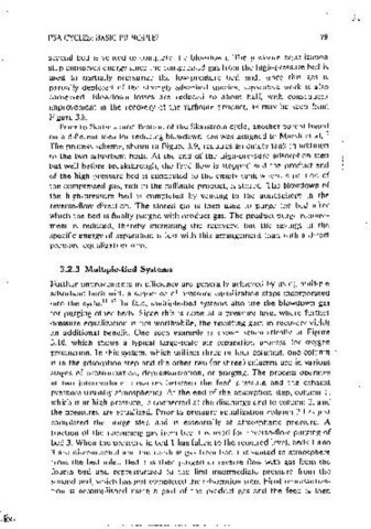
conserved. Blowdown losses are reduced to about half, with consequent
u improvement m the recovery of the ratfinate oroduct. as mav be seen from
'
~ 60
~ Figure 3.8.
~
s Pnor to Beriin•s modification of the Skarstrom cycle, another natcnt hasecl
,, on a different idea for rcducmg blowdown loss was assigned to, Marsh et al. rn
0 4-0
The process scheme, shown m Figure 3.9, reauires an empty tank m addition
to the two adsorbent beds. At the end of the high-pressure adsorot1on step
20 but well before breakthrough, the feed flow is stopped and the product end
of the high-pressure bed 1s connected to the empty tank where a portion of
the compressed gas, nch m the raffinate product. iii stored. Toe blowctown of
00 ----=o'=.s,_.---,~.o,_.---1~.s,.....---2~.0----2~.-s- 0 the high-pressure bed is comoieted by venting to the atmosohere m the
reverse-flow direction. The stored gas 1s then used to purge the bed after
Prod. ltow rate (SCFMl
which the bed 1s finally purged with product gas. The product purge reamre-
Figure 3,8 Punty and fractmnal recovcrv of 0 2 ma two-bed PSA a,r separation unit ment ts reduced, thereby mcreasmg the recovery, l)ut the savings m the
showing improvement 111 recovery ohtamcd by mcluston of pressure equaljzatmn step.
(From Rd, 4; rcpnnlcd with pcrm1ssum.) soecific energy of separation Is less with this arrangement than with a direct
pressure cqualizal.lon stcn.
3.2.3 Multiple-Bed Systems
RAFFINATE PRODUCT
Further improvements m eflic1ency arc generally achieved by using multioic
adsorbent beds with a seauence of oressure eaualizatton steps incorporated
mto the cycle. 11 12 In fact, multiole-bed systems also use the blowdown gas
•
for purging other beds. Since this is done at a pressure level where further
pressure equalization is not worthwhile, the resulting gain m recoverv vields
an additional benefit. One such example Is shown schemat1cally in Figure
3.10, which shows a typical large-scale air separation process for oxygen
oroduction. In this system. which utilizes three or four columns, one column
1s m the actsorotion step and the other two for three) columns are m various
stages of pressurization, depressurization. or purging. The process operates
at two intermediate pressures between the feed pressure and the exhaust
pressure (usually atmospheric). At the end of the 'adsorption step, column i,
which 1s at high pressure, Is connected at the discharge end to coiumn 2, and
the pressures are equalized. Pnor to pressure eaualizat10n column 2 has Just
VENT completed the purge step and 1s essentially at· atmosphenc pressure. A
fraction of the remaining gas from bed i 1s used for reverse-flow purging of
bed 3. When the pressure in bed 1 has fallen to the reauired level, beds I and
3 are disconnected and the residual gas from bed, l ts vented to atmosphere
from the bed mlet. Bed 1 1s then purged in reverse flow with gas from the
FEED fourth bed and repressurized to the first intermediate pressure from the
second bed, which has JUSt compieted the adsorption step. Final repressuriza-
Figure 3.9 Schematic diagram of a PSA cycle showing the use of a third empty tank
for rcducmg blowdown ioss. tlon 1s accomplished using a part of the product gas and the feed 1s then