
Page 272 - Pressure Swing Adsorption
P. 272
, Ii
248 PRESSURE SWING ADSORPTION PSA PROCESSES 249
with any CO 2 that has passed through A bed. This step is terminated
Just orior to breakthrough of the C mass transfer front.
2
A2. CO 2 Rinse. At the termmallon of the adsorpt10n .step high-puntv CO
2
teed at the feed gas pressure 1s passed through the bed m the cocurrent
Y==Yco~ direction. The effluent has a composition similar to that of the feed, and
i 1t JS recycled as feed to another of the A beds. This step 1s contmuect
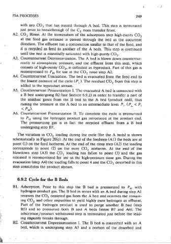
SOLID PHASE I until the bed 1s essentially saturated with high-purity CO~.
LOADING A3. Countercurrent Depressunzation. The A bed is blown down countercur-
rently to atmospheric pressure, and the effluent from this step, which
i - l:.NO OF THE FEED STEP consists of high-purity CO , 1s collected as byproduct. Part of this gas 1s
2
2 - END OF THE HIGH PRESSURE RINSE STEP recomoressed to PH for use m the CO nnse step AZ.
2
3 - END OF THE DEPRESSURIZATION STEP A4. Countercurrent Evacuation. The bed 1s evacuated from the feed end to
- the lowest pressure or the cycie (PL). The residual CO from this step 1s
4 - END OF THE EVACUATION STEP
2
added to the byproduct stream.
PRESSURE AS. Countercurrent Pressurization I. The evacuated A bed is connected with
(c) a B beet unctergomg B2 (see Section 6.9.2) in order to transfer a oart of
the residual gases from the B beet to the A beet (product end), thus
Figure 6.20(c) Variation in CO loading during the cycle for the Gemmi-9 Process. ra1smg the pressure m the A bed to an mtennediate level Pl" (PL< P!
34 2
(From Kumar ei ai., with oerm1ssion.) < PH).
A6. Countercurrent Prcssunzat1on II. To complete the cycle is pressurized
to PH using the hydrogen product gas mtroducect at the product end.
process, can be recovered as a valuable byproduct. A PSA process for The pressunzmg gas 1s m fact the recycled effluent from a B bed
simultaneous production of pure· hydrogen and carbon dioxide from such a unctergomg step B7.
feed gas has recently been developed by Air Products and is described here
as an example of the third generat10n of PSA processes designed to achieve The vanation m CO loading during the cvcle (for the A beds) is shown
2
both energy effi.c1ency and ctuai product recovery. Two variants of this process schematically m Figure 20(c). At the end of the feedstep (Al) the beds are at
have been developed. The ongmal versi.on (Gemini-9) 17 33 used nine adsor- pomt (1) on the feed isotherm. At the end of the rinse step (A2) the loading
•
bent beds m a senes-parallel arrangement but m tile later version improved corresponds to point (2) on the pure CO 2 isotherm. At tile end of the
performance was obtained, at a somewhat tower camtal cost, by using a blowctown step (A3) the CO 2 loading has fallen to p01nt (3) and the gas
modified cycle with only eight beds (Gemini-8). 34 released is recompressed for use as the high-pressure tinse gas. During tile
The flowsheet for Gemmi-9 1s shown schemaucally m Figure 6.20. There evacuation (step A4) the loading falls to pomt 4 and the CO ctesorbed in this
2
are siX parallel beds contaming a zeolite adsorbent (NaX) that selectively step constitutes the oroduct stream.
removes H 0 and CO from the feed gas (the A beds) and three parallel
2 2
beds pacKect with a second zeolite adsorbent (a mixture of NaX and 5A) that
6.9.2 Cycle for the B Beds
selectively removes CO , co; CH , and N 1mpurities from the hydrogen
2 4 2
product (the B beds). During the adsorotion steps one A and one B bed are Bl. Adsorption. Pnor to this step the 8 bed is pressurized to P with
11
connected in series. but the desorption steps for the A and B beds are hydrogen product gas. The B bed in series with an A bed during step A 1
different, as will be described. receives the CO depleted gas from the A bed and removes the remam-
2
mg CO 2 and other impurities to yield highly pure hydrogen as effluent.
Part of the hydrogen producJ 1s used to purge another B bed (step
6.9.1 Cycle for the A Beds
85) and to pressurize both B and A beds (steps B7 and A6). The
Al. Adsorption. Follow mg pressunzation with the hydrogen-rich product gas adsorotion/oroctuct withdrawal step is terminated Just before the lead-
the feed gas is passed through the bed at the highest pressure of the mg impunty breaks through.
cycle (PH). CO and water vapor are removed, and the effluent passes to B2. Countercurrent Depressunzation I. The B bed 1s connected with an A
2
a B bed for removal of the trace impurities (CO, CH 4 , and N 2 ) together beet, which JS unctergomg step A5 and a oortJon of the desorbed and