
Page 268 - Pressure Swing Adsorption
P. 268
244 PRESSURE SWING ADSORPTION PSA PROCESSES 245
Table 6.4. Performance of Bergbau VSA Process for Recovery of.CO 2 from Flue Gas
t
Run I Run 2 Run 3
""'"
OCT-"'E
1
Compressor Pl (m· /h) 65 65 65 I eROOUCT
Compressor P2 (m' /h) 350 160 100 n
CO puntv (%) 98.8 98.6 98.7 '
2 DESOfiPTION ,OS()RPTI()N
Product rate (kg/h) 5.9 4.8 4.1
Recoverv (%) 72 62 53 L,J
Total energy of Pl + P2 3.0 1.0 0.8
kW/hkg CO 2
Feed: flue gas contammg ~ I I vol% CO at 36 m·' /h (STP); adsorber: four beds, each 96 liters packed
2
I
with wide-pore CMS.
So!lrc.-; Ref. 30.
molecular sieves, a vacuum desorption system 1s necessary. A high setectlv1ty SEP»IATOFI
for CO is achieved by the use of a narrow-pore carbon molecular sieve
I
=-
2 LOW
. adsorbent, similar to that used for mtrogen oroduction. However, the process @----------.J, .........
differs from the nitrogen orocess m that the product (CO 2 ) is the more mo
strongly adsorbed component. A s1mpie two-bed vacuum swing system oper- {a)
ating between about 1.2 and 0.05 atm has been developed and built at a
Japanese steel works. 31 The process schematic 1s shown m Figure 6.17. 99%
3
product punty and a recovery of 80% at a product rate of 3000 N m /h are
claimed. A more complex four:bed version of this process has also been
developed to the pilot plant stage. 32 The schematic of the process 1s shown m
Figure 6.18 and perfonnance data are given in Table 6.4. As a result of
environmental pressures the possibility of extracting CO 2 from the stack
gases of coal-fired power stations is under active study at the pilot plant
stage,31 although, with current technoiogy, the power costs are too high to SEO SED
make such a process econom1cally attractive.
6. 7 Recovery of Methane from Landfill Gases
A somewhat similar process has been developed for recovery of methane FED>
\'ACUL'!'i OESOIIPTI0:--1
from· Jandfill gases. 12 13 · These gases contam mamly methane (50-65%) and
•
carbon dioxide (35-50%) as well as small amounts of nitrogen, with many
CYCLE SEQUENCE CHART
diffcirent hydrocarbons and sulfur compounds m trace concentratmns. A
two-stage mitial purification process ts employed. In the first stage hydrogen MlSOJl8£1l l ADSORP1'[0N "~"""" ·I :VACUUM J
DEPUSSUAI-
IIEPRl!:SSUlll-
UTION ·DtSOflPTIOl'il tATibN
sulfide is removed at a temperature of 40-50° C usmg a bed of iodine-im- COCURRE!IT lACI.JUH ·I REPRUSURI-
MISORlllCR 2 0EPR£SSURI- DESQ,i.PTION 1A"l'ION AOSOIIITICHf
pregnated activated carbon. This acts as an efficient catalyst for conversion to ZA1'10N
elemental sulfur, and residual H S levels as low as 1 ppm can be achieved. In (b)
2
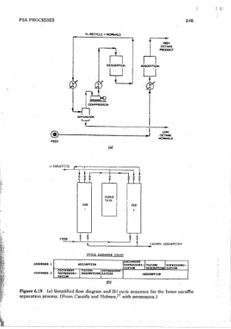
the second stage hatocarbons and heavier hydrocarbons are removed in a Figure 6.19 (a) Simolified flow diagram and (b) cycle sequence for the Isos 1v paraffin
conventional activated carbon adsorber. The 'final stage of the process utilizes separation process. (From Cassidy and Holmes, 27 with perm1ss10n.)
a four-bed vacuum swmg system to recover methane from the purified landfill
gas using a narrow-pore carbon molecular sieve. The remainmg impurities