Page 265 - Pressure Swing Adsorption
P. 265

242                                    PRESSURE SWING ADSORPTION                 PSA PROCESSES
                                                                                                                                                         243
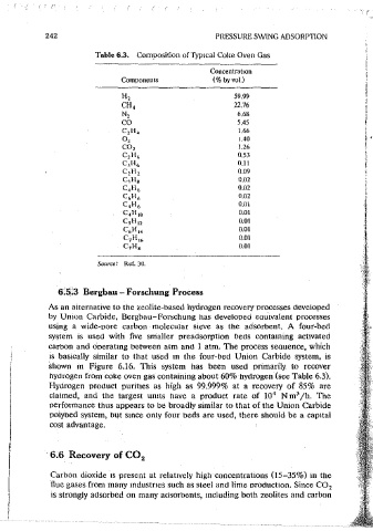
                       Table 6.3.  Composition of Typical Coke Oven Gas
                                                                                                                                "'OSie  gos
                                                 Concentration
                            Components           (% by vol.)
                             H,                       59.99
                                                                                                                                adsorption  pressure
                             CH,                      22.76                                                                       i.i  -  1.J  bar
                             N,                        6.68                                                              co,
                             co                        5.45
                             C 2 H,1                   1.66                                               feed
                             o,                        J.40                                               gas
                             co,                       1.26
                             C 2 H{,                   0.53                                                   blower
                             c_,H,,                    0.11
                             C2H2                      0.09
                                                       0.02
                             C 1 H 8
                                                                                                                                final  desorption
                             C 4 H1,                   0.02                                                                     pressure:
                             C<iHo                     0.02                                                                     approx.  50  mbor
                             C4Ho                      0.01
                             C 4 H  10                 0.01
                             CsH12                     0.01                                                                     vacuum
                                                                                                                                pump
                             Ct,H14                    0.01                                                                           product  gos
                             C 7 Hu,                   0.01
                             C7Hs                      0.01                                                                              co,
                                                                                                                                    (>997.  by  vol.)
                       Source:'  Ref. 30.                                                   Figure 6.17  Schematic of vacuum swmg  process for  CO recovery from  the effluent
                                                                                                                                       2
                                                                                            gas from a steel works. (From Schr5ter and Jiimgen,  with permission.)
                                                                                                                                   12
              6.5!3  Bergbau - Forschung Process
            As  an alternative to the zeolite-based hydrogen recovery orocesses developed
            by  Union  Carbide,  Bergbau-Forschung has  developed  eau1vaient  processes         (i)!co2-9enerationl  (D~
            using  a  wide~oore  carbon  molecular  sieve  as  the  adsorbent.  A  four-bed
                                                                                                    flue  gas
            system  is  used  with  five  snialler  preadsorption  beds  contaming  activated
            carbon  and Ooerat10g  between  atm and  1 atm. The process seQuence, which
            is  basically  similar  to  that  used  m  the  four-bed  Union  Carbide  system.  is
            shown  m  Figure  6.16.  This  system  has  been  used  orimarily  to  recover
            hydrogen from coke oven gas containing about 60% hydrogen (see Table 6.3).
            Hydrogen  oroduct  purittes  as  high  as  99.999%  at  a  recovery  of 85%  are
                                                                    3
            claimed,  and  the  largest  units  have  a  product  rate  of  10 4   N m /h.  The
            oerformance thus appears to be broadly similar to that of the Union Carbide
            poiybed system, b1Jt  smce only four beds are used, there should  be  a cap1tai
            cost advantage.


            6.6  Recovery of CO
                                 2                                                                            ~---'~--'~---'i'----~
                                                                                                                                               \dp~~W·
                                                                                                                                                PZ
             Carbon dioxide  1s  present  at  relatively  high  concentrations (15-35%) in  the
            flue gases from  many mdustnes such as steel and lime oroctuction. Since CO 2   Figure 6.18  Scilemat1c  diagram  of a  four~hed  vacuum  i;Wmg  system  for  recoverv  of
             ts  strongly adsorbed on many adsorbents, mcluding both zeolites and carbon   CO2  from  flue  gas. (From  Pilarczyk  and Schrt'iter, u  with  permission.)   -
   260   261   262   263   264   265   266   267   268   269   270