
Page 44 - Principles and Applications of NanoMEMS Physics
P. 44
30 Chapter 1
1.2.3.4.1 Scanning Tunneling Microscope
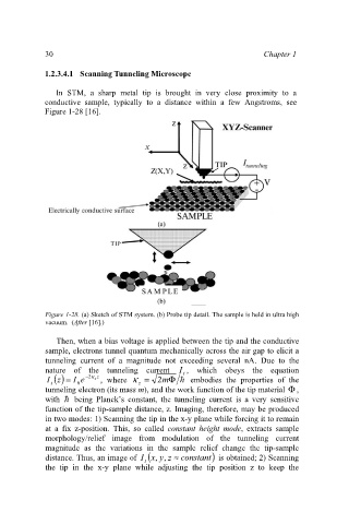
In STM, a sharp metal tip is brought in very close proximity to a
conductive sample, typically to a distance within a few Angstroms, see
Figure 1-28 [16].
Figure 1-28. (a) Sketch of STM system. (b) Probe tip detail. The sample is held in ultra high
vacuum. (After [16].)
Then, when a bias voltage is applied between the tip and the conductive
sample, electrons tunnel quantum mechanically across the air gap to elicit a
tunneling current of a magnitude not exceeding several nA. Due to the
nature of the tunneling current I , which obeys the equation
t
I () Iz = e − 2 z κ z , where κ = 2 m Φ = embodies the properties of the
t 0 z
tunneling electron (its mass m), and the work function of the tip material Φ ,
with = being Planck’s constant, the tunneling current is a very sensitive
function of the tip-sample distance, z. Imaging, therefore, may be produced
in two modes: 1) Scanning the tip in the x-y plane while forcing it to remain
at a fix z-position. This, so called constant height mode, extracts sample
morphology/relief image from modulation of the tunneling current
magnitude as the variations in the sample relief change the tip-sample
distance. Thus, an image of ( yxI , , z ≈ constant ) is obtained; 2) Scanning
t
the tip in the x-y plane while adjusting the tip position z to keep the