
Page 213 - Principles of Applied Reservoir Simulation 2E
P. 213
198 Principles of Applied Reservoir Simulation
be a fault block bounded upstructure and to the east by an unconformity;
downstructure and to the west by a fault or aquifer; and to the north and south
by sealing faults.
Depth A
(ft) A
""*^~ DoO ""•"•HP* 1 "' W *• " r "
T * „
Well
_920o P- 1 . - " , : ' • "
Seismic Reflectors
(Processed with time-
_9600 .•.'•" . • " depth conversion) _
i » "i i i i i i 1 1
0 400 800 1200 1600 2000
Distance from Western Fault (ft)
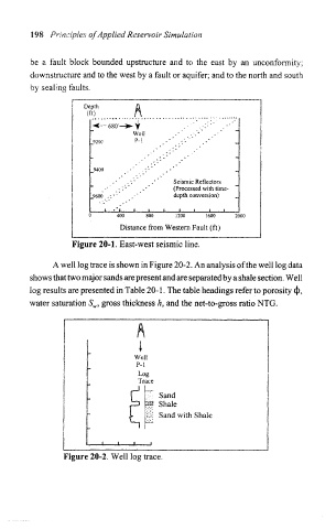
Figure 20-1. East-west seismic line.
A well log trace is shown in Figure 20-2. An analysis of the well log data
shows that two major sands are present and are separated by a shale section. Well
log results are presented in Table 20-1. The table headings refer to porosity <|>,
water saturation S w, gross thickness h, and the net-to-gross ratio NTG.
Well
P-l
Log
Trace
Sand
' Shale
&! Sand with Shale
Figure 20-2. Well log trace.