
Page 230 - Principles of Applied Reservoir Simulation 2E
P. 230
Part III: Case Study 215
21.5 Grid Preparation
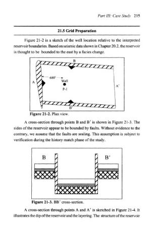
Figure 21-2 is a sketch of the well location relative to the interpreted
reservoir boundaries. Based on seismic data shown in Chapter 20.2, the reservoir
is thought to be bounded to the east by a facies change.
Figure 21-2. Plan view,
A cross-section through points B and B' is shown in Figure 21-3. The
sides of the reservoir appear to be bounded by faults. Without evidence to the
contrary, we assume that the faults are sealing. This assumption is subject to
verification during the history match phase of the study.
B
Figure 21-3. BB' cross-section.
A cross-section through points A and A' is sketched in Figure 21-4. It
illustrates the dip of the reservoir and the layering. The structure of the reservoir