
Page 103 - Process Equipment and Plant Design Principles and Practices by Subhabrata Ray Gargi Das
P. 103
100 Chapter 4 Shell and tube heat exchanger
Fixed tube sheet:
(4.31a)
L e ¼ L 2 TS; ð 1Þ
Floating head:
(4.31b)
L e ¼ L 2 TS XLZ; ð 2Þ
U-tube
(4.31c)
L e ¼ L TS XU; ð 3; 4Þðnozzle at=after U-bendÞ
and
(4.31d)
L e ¼ L TS 50 mm; ð 5; 6Þðnozzle before U-bendÞ
( 1) Calculation of TS discussed in next section.
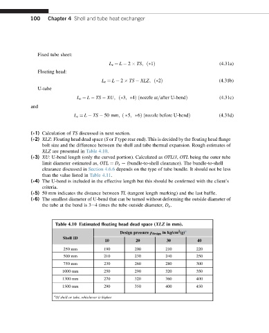
( 2) XLZ: Floating head dead space (S or T type rear end). This is decided by the floating head flange
bolt size and the difference between the shell and tube thermal expansion. Rough estimates of
XLZ are presented in Table 4.10.
( 3) XU: U-bend length (only the curved portion). Calculated as OTL/3, OTL being the outer tube
limit diameter estimated as, OTL ¼ D s e (bundle-to-shell clearance). The bundle-to-shell
clearance discussed in Section 4.6.6 depends on the type of tube bundle. It should not be less
than the value listed in Table 4.11.
( 4) The U-bend is included in the effective length but this should be confirmed with the client’s
criteria.
( 5) 50 mm indicates the distance between TL (tangent length marking) and the last baffle.
( 6) The smallest diameter of U-bend that can be turned without deforming the outside diameter of
the tube at the bend is 3e4 times the tube outside diameter, D o .
Table 4.10 Estimated floating head dead space (XLZ in mm).
2
Design pressure p design in kg/cm (g) a
Shell ID
10 20 30 40
250 mm 190 200 210 220
500 mm 210 230 240 250
750 mm 230 260 280 300
1000 mm 250 290 320 350
1300 mm 270 320 360 400
1500 mm 290 350 400 450
a
Of shell or tube, whichever is higher.