
Page 104 - Process Equipment and Plant Design Principles and Practices by Subhabrata Ray Gargi Das
P. 104
4.6 Mechanical detailing 101
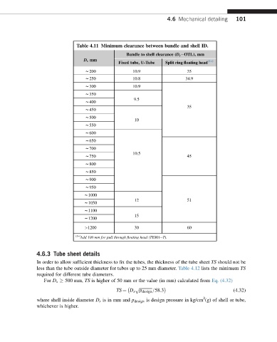
Table 4.11 Minimum clearance between bundle and shell ID.
Bundle to shell clearance (D s eOTL), mm
D s mm
Fixed tube, U-Tube Split ring floating head (1 )
w200 10.9 35
w250 10.8 34.9
w300 10.9
w350
9.5
w400
35
w450
w500
10
w550
w600
w650
w700
10.5
w750 45
w800
w850
w900
w950
w1000
12 51
w1050
w1100
15
w1200
>1200 30 60
(1 )
Add 100 mm for pull through floating head (TEMAeT).
4.6.3 Tube sheet details
In order to allow sufficient thickness to fix the tubes, the thickness of the tube sheet TS should not be
less than the tube outside diameter for tubes up to 25 mm diameter. Table 4.12 lists the minimum TS
required for different tube diameters.
For D s 500 mm, TS is higher of 50 mm or the value (in mm) calculated from Eq. (4.32)
p ffiffiffiffiffiffiffiffiffiffiffiffiffi
TS ¼ D s p design =58:3 (4.32)
2
where shell inside diameter D s is in mm and p design is design pressure in kg/cm (g) of shell or tube,
whichever is higher.