
Page 107 - Process Equipment and Plant Design Principles and Practices by Subhabrata Ray Gargi Das
P. 107
104 Chapter 4 Shell and tube heat exchanger
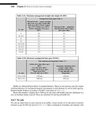
Table 4.13a Maximum unsupported straight tube length (IS 4503).
Unsupported length upper limit, m
Material of tube e carbon and high
alloy steels up to 400 C/Light alloy
steels up to 450 C/NickeleCopper
up to 315 C/Nickel up to 450 C/ Material of tube e aluminium
Nickelechromiumeiron up to and aluminium alloys/Copper
D o ,mm
540 C and copper alloys
6 0.6 0.5
10, 10.2 0.8 0.7
12 1.1 0.9
16 1.3 1.1
18, 19, 20 1.5 1.3
25, 25.4 1.8 1.6
31.8, 32 2.2 1.9
38, 40 2.5 2.2
Table 4.13b Maximum unsupported tube span (TEMA).
Tube material and temperature limits ( C)
Carbon steel, other alloys up to
400 C Aluminium, aluminium alloys
Low alloy up to 455 C Copper, copper alloys
Copperenickel up to 316 C Titanium, titanium alloys
Nickel up to 454 C @ code allowable max.
D o ,mm Ni-Cr-Fe alloy up to 538 C Temperature
19.0 or 19.05 1525 mm 1320 mm
25.0 or 25.4 1880 mm 1625 mm
Baffles are fabricated from sheets of standard thickness. These are not pressure parts but require
sufficient thickness for mechanical integrity that depends on shell diameter as well as baffle spacing.
Required baffle thickness according to IS 4503 is presented in Table 4.14.
Removable bundles weighing above 5450 kg are provided with bundle skid bars (minimum two
nos.) to facilitate bundle removal. These bars protrude 0.8 mm beyond baffle OD.
4.6.7 Tie rods
Tie rods are made from the same material as the baffles. Actual number of tie rods and its minimum
diameter as per IS:4503 are listed in Table 4.15. Other combinations of number and diameter with