
Page 111 - Process Equipment and Plant Design Principles and Practices by Subhabrata Ray Gargi Das
P. 111
108 Chapter 4 Shell and tube heat exchanger
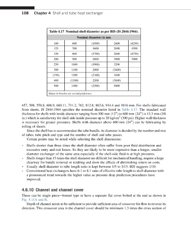
Table 4.17 Nominal shell diameter as per BIS (IS 2844:1964).
Nominal diameters in mm
100 600 (1500) 2400 (4250)
125 700 1600 2600 4500
150 800 (1700) 2800 (4750)
200 900 1800 3000 5000
250 1000 (1900) 3200
300 1100 2000 (3400)
(350) 1200 (2100) 3600
400 (1300) 2200 (3800)
500 1400 (2300) 4000
Values in bracket are second preference.
457, 508, 558.8, 606.9, 660.11, 711.2, 762, 812.8, 863.6, 914.4 and 1016 mm. For shells fabricated
from sheets, IS 2844:1964 specifies the nominal diameter listed in Table 4.17. The standard wall
thickness for shells with inside diameter ranging from 300 mm ð12 Þ to 600 mm ð24 Þ is 13.3 mm (3/8
00
00
2
in.) which is satisfactory for shell side inside pressure up to 20 kg/cm (300 psi). Higher wall thickness
is necessary for greater pressures. Shells with diameter above 600 mm ð24 Þ can be fabricating by
00
rolling of sheets.
Since the shell has to accommodate the tube bundle, its diameter is decided by the number and size
of tubes, tube pitch and type and the number of shell and tube passes.
Certain points may be noted while selecting the shell dimensions:
- Shells shorter than three times the shell diameter often suffer from poor fluid distribution and
excessive entry and exit losses. So they are likely to be more expensive than a longer, smaller
diameter exchanger of the same area especially if the shell-side fluid is at high pressures.
- Shells longer than 15 times the shell diameter are difficult for mechanical handling, require a large
clearway for bundle removal or retubing and show the effects of diminishing return on costs.
- Usually shell diameter to tube length ratio is kept between 1/5 to 1/15. BIS suggests 1/10.
- Conventional heat exchangers have 6:1 or 8:1 ratio of effective tube length to shell diameter with
a pronounced trend towards the higher value as pressure drop prediction procedures have
improved.
4.6.10 Channel and channel cover
These can be single pieceebonnet type or have a separate flat cover bolted at the end as shown in
Fig. 4.11A and B.
Depth of channel needs to be sufficient to provide sufficient area of crossover for flow to reverse its
direction. This crossover area in the channel cover should be minimum 1.3 times the cross section of