
Page 108 - Process Equipment and Plant Design Principles and Practices by Subhabrata Ray Gargi Das
P. 108
4.6 Mechanical detailing 105
X
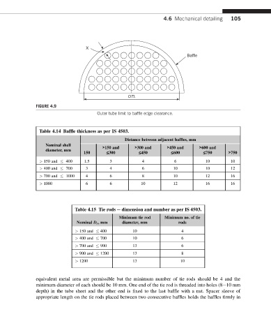
Baffle
OTL
FIGURE 4.9
Outer tube limit to baffle edge clearance.
Table 4.14 Baffle thickness as per IS 4503.
Distance between adjacent baffles, mm
Nominal shell >150 and >300 and >450 and >600 and
diameter, mm
150 £300 £450 £600 £750 >750
> 150 and 400 1.5 3 4 6 10 10
> 400 and 700 3 4 6 10 10 12
> 700 and 1000 4 6 8 10 12 16
> 1000 6 6 10 12 16 16
Table 4.15 Tie rods e dimension and number as per IS 4503.
Minimum tie rod Minimum no. of tie
Nominal D s ,mm diameter, mm rods
> 150 and 400 10 4
> 400 and 700 10 6
> 700 and 900 13 6
> 900 and 1200 13 8
> 1200 13 10
equivalent metal area are permissible but the minimum number of tie rods should be 4 and the
minimum diameter of each should be 10 mm. One end of the tie rod is threaded into holes (8e10 mm
depth) in the tube sheet and the other end is fixed to the last baffle with a nut. Spacer sleeve of
appropriate length on the tie rods placed between two consecutive baffles holds the baffles firmly in