
Page 105 - Process Equipment and Plant Design Principles and Practices by Subhabrata Ray Gargi Das
P. 105
102 Chapter 4 Shell and tube heat exchanger
For D s < 500 mm, TS is higher of D s =10 or the value calculated from Eq. (4.32).
Typically, for design, the thickness of each tube sheet may be estimated from experience as 38 mm
2
for low-pressure units and 50e150 mm for high-pressure exchangers (14e27 kg/cm ).
Effective tube sheet thickness for strength calculation is measured from bottom of pass partition
groove minus shell-side corrosion allowance and corrosion allowance on the tube side in excess of the
groove depth. Tube sheet thickness calculation based on strength is not included here and the detailed
calculation may be referred from Appendix 7 of IS 4503 or from the TEMA code.
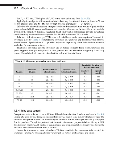
Tube sheet hole diameter as per TEMA code is decided based on the chosen option of ‘standard fit’
or ‘special close fit’. Table 4.12 includes the tube sheet hole diameter and its tolerance for different
tube diameters. ‘Special close fit’ is provided only when required by client. It is used for austenitic
steel tubes for corrosion resistance.
Blind holes are drilled into the tube sheet and are tapped to create thread to attach tie rods and
spacer supports. Pass partition plates are also grooved into the tube sheet e typically 5 mm deep
groove. Typical depth of groove in tube sheet for rolling of tubes is 3 mm.
Table 4.12 Minimum permissible tube sheet thickness.
Permissible deviation in
hole diameter, mm
Minimum Standard fit hole Special close fit
D o ,mm TS,mm diameter, mm hole diameter, mm Standard Special
fit close fit
6 6 D o þ 0:2 D o þ 0:15 0.1 0.05
10 10 D o þ 0:2 D o þ 0:15 0.1 0.05
12 12 D o þ 0:2 D o þ 0:15 0.1 0.05
16 13 D o þ 0:2 D o þ 0:15 0.1 0.05
18, 19, 20 15 D o þ 0:2 D o þ 0:15 0.1 0.05
25, 25.4 19 D o þ 0:3 D o þ 0:2 0.1 0.05
31.8, 32 22.4 D o þ 0:4 D o þ 0:3 0.1 0.05
38, 40 25.4 D o þ 0:5 D o þ 0:4 0.2 0.08
4.6.4 Tube pass pattern
Pass patterns in the tube sheet can be Ribbon, H-banded (or mixed) or Quadrant as shown in Fig. 4.8.
During tube sheet layout, it may not be possible to provide exactly same number of tubes per pass. The
choice of pass pattern is based on minimising the deviation in tube counts per pass and pass by-pass
flow in pass-lane. Though the preferable deviation in tube counts per pass is below 5%, up to 10%
deviation may be allowed. H-banded or quadrant pass-lane arrangements have lower bypass flow in the
pass-lane when the baffle orientation is vertical.
In case the tube count per pass varies above 5%, flow velocity in the passes need to be checked for
limitations in velocity. This is particularly important for flow of cooling water and slurry.