
Page 109 - Process Equipment and Plant Design Principles and Practices by Subhabrata Ray Gargi Das
P. 109
106 Chapter 4 Shell and tube heat exchanger
D Ø
n
Impingement
Baffle (W ×L )
IB
IB
H
h t IB
W IB
Inner face
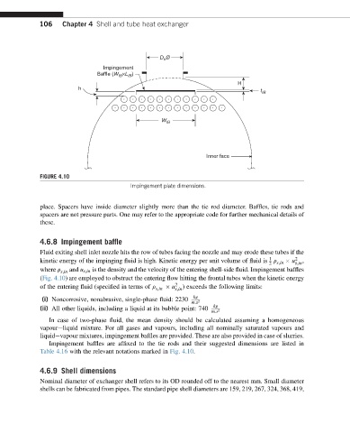
FIGURE 4.10
Impingement plate dimensions.
place. Spacers have inside diameter slightly more than the tie rod diameter. Baffles, tie rods and
spacers are not pressure parts. One may refer to the appropriate code for further mechanical details of
these.
4.6.8 Impingement baffle
Fluid exiting shell inlet nozzle hits the row of tubes facing the nozzle and may erode these tubes if the
1
kinetic energy of the impinging fluid is high. Kinetic energy per unit volume of fluid is r u 2 ,
2 s;in s;in
where r s;in and u s;in is the density and the velocity of the entering shell-side fluid. Impingement baffles
(Fig. 4.10) are employed to obstruct the entering flow hitting the frontal tubes when the kinetic energy
of the entering fluid (specified in terms of r s;in u 2 s;in ) exceeds the following limits:
kg
(i) Noncorrosive, nonabrasive, single-phase fluid: 2230
m:s 2
kg
(ii) All other liquids, including a liquid at its bubble point: 740
m:s 2
In case of two-phase fluid, the mean density should be calculated assuming a homogeneous
vapoureliquid mixture. For all gases and vapours, including all nominally saturated vapours and
liquidevapour mixtures, impingement baffles are provided. These are also provided in case of slurries.
Impingement baffles are affixed to the tie rods and their suggested dimensions are listed in
Table 4.16 with the relevant notations marked in Fig. 4.10.
4.6.9 Shell dimensions
Nominal diameter of exchanger shell refers to its OD rounded off to the nearest mm. Small diameter
shells can be fabricated from pipes. The standard pipe shell diameters are 159, 219, 267, 324, 368, 419,