
Page 112 - Process Equipment and Plant Design Principles and Practices by Subhabrata Ray Gargi Das
P. 112
4.6 Mechanical detailing 109
(A) (B) Channel
Tube sheet Flat cover
Shell Gasket
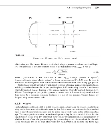
FIGURE 4.11
Channel cover: (A) single piece, (B) flat cover on channel.
all tubes in a pass. The channel thickness is calculated using the pressure vessel design codes (Chapter
17). The same code is used to find the thickness of the flat channel cover t channel in mm as
p ffiffiffiffiffiffiffiffiffiffiffiffiffiffiffiffiffiffiffiffiffiffi
D s C p design
(4.33)
10 f all;stress
t channel ¼
2
where D s ¼ diameter of the shell/cover in mm; p design ¼ design pressure in kgf/cm ;
2
f all;stress ¼ allowable stress value in kgf/mm at design temperature and C ¼ 0:25 when the cover is
bolted with full faced gaskets and C ¼ 0:3 when cover bolted with narrow faced or ring type gaskets.
The thickness is finally arrived at by addition of corrosion allowance margin. Minimum thickness,
including corrosion allowance for the pass partition plates, is 10 mm for alloy channels. It is minimum
10 mm for nominal channel diameter of 600 mm and minimum 13 mm for nominal diameter above
600 mm. Typical depth of pass partition grooves in channel cover is 5 mm as already mentioned and
there should be a minimum remaining thickness of 3 mm of base material. Channel flanges are
designed using pressure vessel code.
4.6.11 Nozzles
Heat exchanger nozzles are sized to match process piping and are based on process considerations
using standard maximum allowable velocity of the fluid. It is economic to make nozzles from standard
pipes of nearest diameter in most cases and the nozzle size is usually same as that of the connecting
pipe. The design practice states that the total nozzle pressure drop for either the shell side or the tube
side should not exceed about 25% of the total, except for low pressure drop services like condensers or
reboilers. In case of one tube pass exchanger, the pressure drop across inlet nozzle of the tube side
should not exceed 25% of the total. This avoids flow maldistribution on the tube side due to high