
Page 115 - Process Equipment and Plant Design Principles and Practices by Subhabrata Ray Gargi Das
P. 115
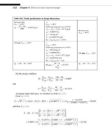
112    Chapter 4 Shell and tube heat exchanger


               Table P4.1 Fluid specifications in design illustration.
               Kerosene inlet,               /
               T h;in ¼ 130 C                T h;avg ¼ 90 C


                   55   710                  (Following properties are at 90 C)

                          ¼ 10:8472 kg s
                     3600                    C pk ¼ C ph ¼ 2:343   10 J kg K
               m h ¼
                                                              3

                                                                             Kerosene exit,
                                             m k ¼ 0:00027 Pa s
                                                                             T h;out ¼ 50 C

                                                         3
                                             r k ¼ 710 kg m
                                             k k ¼ 0:148225 W=mK
                                             Pr k ¼ C pk =ðm c k c Þ¼ 4:2715
               CW exit, T c;out ¼ 45 C       )

                                             T c;avg ¼ 39 C

                                             (Following properties are at 39 C)

                                                           3
                                             r w ¼ 992:22 kg m
                                             m w ¼ 0:000642 Pa s             CW inlet, T c;in ¼ 33 C

                                                              3

                                             C p;w ¼ C pc ¼ 4:18   10 J kg K
                                             k w ¼ 0:62976 W=mK

                                             Pr w ¼ C p;w m w k w ¼ 4:26
               D 1 ¼ 130   45 ¼ 85 C                 85   17                 D 2 ¼ 50   33 ¼ 17 C


                                                            ¼ 42:25 C

                                                        85
                                             DT LMTD ¼
                                                      ln
                                                        17
                For the design condition,
                                         T h;in   T h;out  130   50
                                                              ¼ 6:6667
                                      R ¼           ¼
                                          T c;out   T c;in  45   33
             and
                                         T c;out   T c;in  45   33
                                                              ¼ 0:12371
                                      S ¼           ¼
                                         T h;in   T c;in  130   33
                Assuming single shell pass, we calculate F T from Eq. (4.3).
                From Eq. (4.4),
                                                q ffiffiffiffiffiffiffiffiffiffiffiffiffiffiffiffiffiffiffiffiffiffiffiffiffiffiffiffi
                  p ffiffiffiffiffiffiffiffiffiffiffiffiffiffi                                    1   0:12371
                                                         2
                     2                            ð6:6667Þ þ 1   ln                   ¼ 10:849
               X ¼  R þ 1   lnfð1   SÞ=ð1   RSÞg ¼
                                                                  1  ð6:6667   0:12371Þ
             and from Eq. (4.5),

                                      8                        9
                                                       p ffiffiffiffiffiffiffiffiffiffiffiffiffiffi
                                                         2
                                                        R þ 1 =
                                      <2   S   R þ 1
                        Y ¼ðR   1Þ  ln

                                                       p ffiffiffiffiffiffiffiffiffiffiffiffiffiffi
                                                        R þ 1
                                      :                  2     ;
                                        2   S   R þ 1 þ

                                                                      2
                                                               p ffiffiffiffiffiffiffiffiffiffiffiffiffiffiffiffiffiffiffiffiffiffiffiffi
                                                                 6:6667 þ 1
                                      2   0:12371   6:6667 þ 1
                          ¼ 5:6667   ln                                      ¼ 12:236
                                                               p ffiffiffiffiffiffiffiffiffiffiffiffiffiffiffiffiffiffiffiffiffiffiffiffi
                                                                      2
                                                                 6:6667 þ 1
                                      2   0:12371   6:6667 þ 1 þ