Page 114 - Process Equipment and Plant Design Principles and Practices by Subhabrata Ray Gargi Das
P. 114

4.7 Design illustration  111


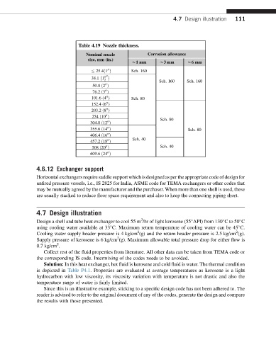
                                Table 4.19 Nozzle thickness.
                                   Nominal nozzle          Corrosion allowance
                                   size, mm (in.)
                                                    w1mm       w3mm       w6mm
                                           00       Sch. 160
                                       25:4ð1 Þ

                                     38:1 1 1 00
                                          2
                                                               Sch. 160   Sch. 160
                                          00
                                     50:8 ð2 Þ
                                          00
                                     76:2 ð3 Þ
                                                    Sch. 80
                                          00
                                     101:6 ð4 Þ
                                          00
                                     152:4 ð6 Þ
                                          00
                                     203:2 ð8 Þ
                                          00
                                                                Sch. 80
                                     254 ð10 Þ
                                           00
                                    304:8 ð12 Þ
                                                                          Sch. 80
                                           00
                                    355:6 ð14 Þ
                                           00
                                    406:4 ð16 Þ
                                                     Sch. 40
                                           00
                                    457:2 ð18 Þ
                                                                Sch. 40
                                          00
                                     508 ð20 Þ
                                           00
                                    609:6 ð24 Þ
               4.6.12 Exchanger support
               Horizontal exchangers require saddle support which is designed as per the appropriate code of design for
               unfired pressure vessels, i.e., IS 2825 for India, ASME code for TEMA exchangers or other codes that
               may be mutually agreed by the manufacturer and the purchaser. When more than one shell is used, these
               are usually stacked to reduce floor space requirement and also to keep the connecting piping short.
               4.7 Design illustration
                                                        3
               Design a shell and tube heat exchanger to cool 55 m /hr of light kerosene (55 API) from 130 Cto 50 C


               using cooling water available at 33 C. Maximum return temperature of cooling water can be 45 C.


                                                                                             2
                                                       2
               Cooling water supply header pressure is 4 kg/cm (g) and the return header pressure is 2.5 kg/cm (g).
                                               2
               Supply pressure of kerosene is 6 kg/cm (g). Maximum allowable total pressure drop for either flow is
                       2
               0.7 kg/cm .
                  Collect rest of the fluid properties from literature. All other data can be taken from TEMA code or
               the corresponding IS code. Intermixing of the codes needs to be avoided.
                  Solution: In this heat exchanger, hot fluid is kerosene and cold fluid is water. The thermal condition
               is depicted in Table P4.1. Properties are evaluated at average temperatures as kerosene is a light
               hydrocarbon with low viscosity, its viscosity variation with temperature is not drastic and also the
               temperature range of water is fairly limited.
                  Since this is an illustrative example, sticking to a specific design code has not been adhered to. The
               reader is advised to refer to the original document of any of the codes, generate the design and compare
               the results with those presented.
   109   110   111   112   113   114   115   116   117   118   119