
Page 113 - Process Equipment and Plant Design Principles and Practices by Subhabrata Ray Gargi Das
P. 113
110 Chapter 4 Shell and tube heat exchanger
velocity head. Too high pressure drop in nozzles lead to a jetting action that may cause flow
2
maldistribution. For axial nozzles to avoid tube end erosion, the r u value should be below
2
8930 kg/m s . Table 4.18 can be used as a guide for nozzle sizing. Nozzle thickness and all flange
designs are based on pressure vessel design codes e ASME (for TEMA) and IS 2825 (for IS 4503).
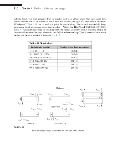
Table 4.19 contains guidelines for selecting nozzle thickness. Generally, the hot side fluid should be
introduced from top to bottom and the cold side fluid from bottom to top. Typical nozzle orientation for
the hot and the cold streams is shown in Fig. 4.12.
Table 4.18 Nozzle sizing.
Shell diameter mm(in.) Nominal nozzle diameter mm (in.)
101.6e254 (4e10) 50.8 (2)
305e438.15 (12e17.25) 76.2 (3)
489e539.75 (19.25e21.25) 101.6 (4)
584.2e736.6 (23e29) 152.4 (6)
787.4e940 (31e37) 203.2 (8)
990.6e1066.8 (39e42) 254 (10)
Multipass
T h,in T c,out
T c,out T h,in T h,in T c,out
T c,in T h,out T h,out T c,in
T T
Single Pass h,out c,in
T h,in T c,out T h,out T c,out
T c,in T h,out T c,in T h,in
Counterflow Co-current flow
FIGURE 4.12
Heat exchanger nozzle orientations for ‘hot’ and ‘cold’ streams.