
Page 106 - Process Equipment and Plant Design Principles and Practices by Subhabrata Ray Gargi Das
P. 106
4.6 Mechanical detailing 103
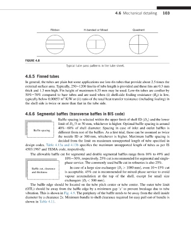
Ribbon H-banded or Mixed Quadrant
FIGURE 4.8
Typical tube pass patterns in the tube sheet.
4.6.5 Finned tubes
In general, the tubes are plain but some applications use low-fin tubes that provide about 2.5 times the
external surface area. Typically, 250e1200 fins/m of tube length is provided and these fins are 0.3 mm
thick and 1.3 mm high. Fin height of maximum 6.35 mm may be used. Low-fin tubes are costlier by
50%e70% compared to bare tubes and are used when (i) shell-side fouling resistance (R d )islow,
2
typically below 0.00053 m K/W or (ii) ratio of the total heat transfer resistance (including fouling) in
the shell side is twice or more than that in the tube side.
4.6.6 Segmental baffles (transverse baffles in BIS code)
Baffle spacing is selected within the upper limit of shell ID ðD s Þ and the lower
limit of D s=5 or 50 mm, whichever is higher. Optimal baffle spacing is around
40%e60% of shell diameter. Spacing in case of inlet and outlet baffles is
Baffle spacing
different from rest of the baffles. As a first trial, these can be assumed as twice
the nozzle ID or 300 mm, whichever is higher. Maximum baffle spacing is
decided from the limit on maximum unsupported length of tube specified in
design codes. Table 4.13a and 4.13b specifies the maximum unsupported length of tubes as per IS
4503:1967 and TEMA code, respectively.
The allowable baffle cut for segmental and double segmental baffles range from 10% to 49% and
10%e30%, respectively. 25% cut is recommended for segmental and single-
phase service. The commonly used baffle cut in refineries is also 25%.
Baffle cut, clearance In case of a large size exchanger ðD s > 1000 mmÞ, even 10w15% cut
and thickness is acceptable. 45% cut is recommended for mixed-phase service to avoid
vapour accumulation at the top of the shell, except for small size
exchangers ðD s < 500 mmÞ.
The baffle edge should be located on the tube pitch centre or tube centre. The outer tube limit
(OTL) should be away from the baffle edge by a minimum gap ‘x’ to prevent breakage due to tube
vibration. This is shown in Fig. 4.9. The periphery of the baffle needs to be away from the shell inside
diameter by a clearance 2x. Minimum bundle to shell clearance required for easy pull out of bundle is
shown in Table 4.11.