
Page 160 - Process Equipment and Plant Design Principles and Practices by Subhabrata Ray Gargi Das
P. 160
5.10 Design illustration 157
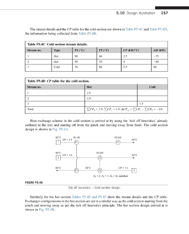
The stream details and the CP table for the cold section are shown in Table P5.4C and Table P5.4D,
the information being collected from Table P5.4B.
Table P5.4C Cold section stream details.
Stream no. Type TS ( C) TT ( C) CP (kW/ C) DH (kW)
1 Hot 90 60 2.5 75
2 Hot 90 30 1 60
3 Cold 20 80 1.5 90
Table P5.4D CP table for the cold section.
Stream no. Hot Cold
1 2.5
2 1.0
3 1.5
P P P P
Total CP h ¼ 3.5; CP c ¼ 1.5; DCP ov ¼ CP c CP h ¼ 2.0
Heat exchange scheme in the cold section is arrived at by using the ‘tick off heuristics’ already
outlined in the text and starting off from the pinch and moving away from there. The cold section
design is shown in Fig. P5.4A.
90°C 30 kW 45 kW
CP = 2.5 60°C
1 E1 C1
90°C 60 kW
CP = 1.0 30°C
2 E2
80°C 60°C CP = 1.5
E1 E2 3
N h = 2, N = 1, N > N satisfied
c
c
h
FIGURE P5.4A
Tick off heuristics e Cold section design.
Similarly for the hot section Tables P5.4E and P5.4F show the stream details and the CP table.
Exchanger configurations in the hot section are set in a similar way as the cold section starting from the
pinch and moving away as per the tick off heuristics principle. The hot section design arrived at is
shown in Fig. P5.4B.