
Page 161 - Process Equipment and Plant Design Principles and Practices by Subhabrata Ray Gargi Das
P. 161
158 Chapter 5 Heat exchanger network analysis
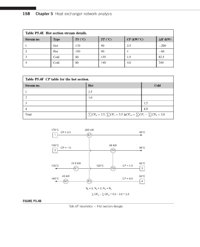
Table P5.4E Hot section stream details.
Stream no. Type TS ( C) TT ( C) CP (kW/ C) DH (kW)
1 Hot 170 90 2.5 200
2 Hot 150 90 1 60
3 Cold 80 135 1.5 82.5
4 Cold 80 140 4.0 240
Table P5.4F CP table for the hot section.
Stream no. Hot Cold
1 2.5
2 1.0
3 1.5
4 4.0
P P P P
Total CP h ¼ 3.5, CP c ¼ 5.5 DCP ov ¼ CP c CP h ¼ 2.0
170°C 200 kW
CP = 2.5 90°C
1 E3
150°C 60 kW
CP = 1.0 90°C
2 E4
22.5 kW 80°C
135°C 120°C CP = 1.5
H1 E4 3
40 kW 80°C
140°C CP = 4.0
H2 E3 4
= 2, N = 2, N = N
c h c
N h
∑ CP C – ∑ CP H = 5.5 – 3.5 = 2.0
FIGURE P5.4B
Tick off heuristics e Hot section design.